
From concept to product
From prototyping to production, our production sites can handle all your manufacturing projects.






Injection Molding
Home / Injection Molding
SOMI Capability
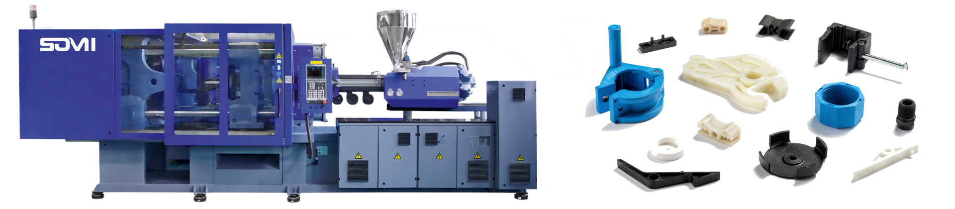
SOMI Injection Molding Capability
Welcome to learn about SOMI's injection molding capabilities! SOMI offers a variety of injection molding types, including Plastic injection molding, Bi-color Injection Molding, and Insert injection molding. With advanced equipment, skilled technicians, and extensive processing experience, we are committed to providing high-quality injection molding services. SOMI's injection molding capabilities are comprehensive, with strategically distributed processing points to efficiently handle various orders.
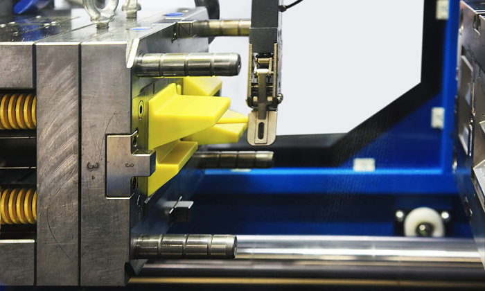
Plastic Injection Molding
Plastic injection molding is a highly efficient and precise manufacturing process that involves injecting molten plastic into molds to create a wide range of complex plastic products.
Low cost, Stable quality.
Short production cycle, Suitable for large-scale production.
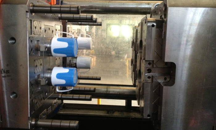
Bi-color Injection Molding
Bi-color injection molding is a specialized process that allows for the production of plastic parts with two different colors or materials in a single operation.
Product appearance diversity, Design flexibility, Cost saving.
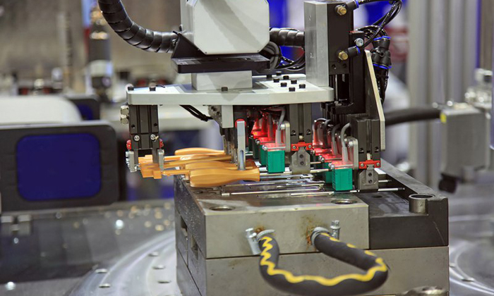
Insert Molding
Insert molding is a specialized injection molding process that involves inserting metal or plastic parts into the mold cavity before the molten material is injected.
Improved part strength and structural integrity.
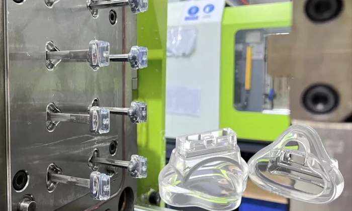
Liquid Silicone Rubber Molding
Liquid Silicone Rubber Molding, also known as LSR molding, is a popular manufacturing process used to create precision silicone rubber parts. This process involves injecting liquid silicone material into a mold cavity, where it is then cured to form the desired product.
Excellent temperature resistance, durability, and chemical stability.
Injection Molding
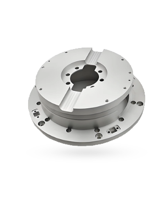
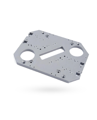
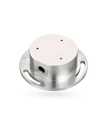
Show Custom Parts Machined by SOMI
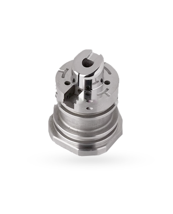
Injection Molding
Injection Molding Materials
SOMI offers a diverse range of surface finishes, each tailored to meet the specific needs of your projects. Here's a closer look at some of the options.
 Common Injection Molding Materials
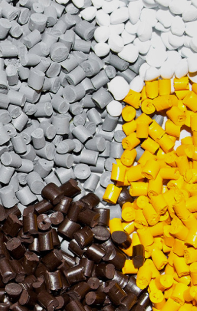

- ABS
It is a thermoplastic polymer material with high strength, good toughness, corrosion resistance, high temperature resistance.

- PVC
It is a thermoplastic polymer material with high strength, good toughness, corrosion resistance, high temperature resistance.

- POM
It is a thermoplastic polymer material with high strength, good toughness, corrosion resistance, high temperature resistance.

- Polypropylene(PP)
It is a thermoplastic polymer material with high strength, good toughness, corrosion resistance, high temperature resistance.

- Nylon
It is a thermoplastic polymer material with high strength, good toughness, corrosion resistance, high temperature resistance.

- PET
It is a thermoplastic polymer material with high strength, good toughness, corrosion resistance, high temperature resistance.

- PTFE(Teflon)
It is a thermoplastic polymer material with high strength, good toughness, corrosion resistance, high temperature resistance.

- FR-4
It is a thermoplastic polymer material with high strength, good toughness, corrosion resistance, high temperature resistance.

- Polycarbonate(PC)
It is a thermoplastic polymer material with high strength, good toughness, corrosion resistance, high temperature resistance.

- PMMA
It is a thermoplastic polymer material with high strength, good toughness, corrosion resistance, high temperature resistance.

- Polyethylene(PE)
It is a thermoplastic polymer material with high strength, good toughness, corrosion resistance, high temperature resistance.

- PEEK
It is a thermoplastic polymer material with high strength, good toughness, corrosion resistance, high temperature resistance.
Injection Molding
Injection Molding Surface Finishes
SOMI offers a diverse range of surface finishes, each tailored to meet the specific needs of your projects. Here's a closer look at some of the options.
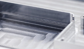
As-machined
The standard finish of our parts, the "machined" finish, has a surface roughness of 3.2 μm (126 μin), which removes sharp edges and cleanly removes burrs from the part.
Machining Texture:There are slight scratches on the visible surface.
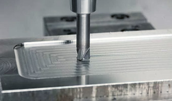
Smooth machining
A finishing CNC machining operation can be applied to the part to reduce its surface roughness. The standard smoothing surface roughness is Ra 1.6 μm (64 μin). Light surface scratches are visible.
Machining Texture:Visible, light surface scratches.
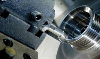
Fine machining
Refers to the process of precision treatment of raw materials or semi-finished products. The standard smoothing surface roughness is Ra 0.8 μm (32 μin).
Machining Texture:Slightly visible.
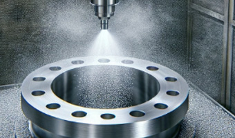
Bead blasting
Bead blasting refers to the use of round spherical media that, when impacted against the surface of a part, will leave a more uniform finish caused by the sphere “dimpling” the surface.
Machining Texture:Frosted grain.
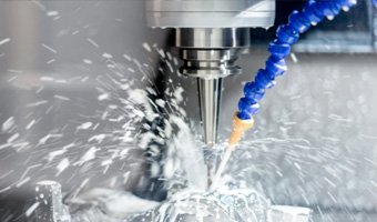
Brushing
Brushing is a surface treatment process that uses abrasive belts to draw traces on the surface of a material, usually for aesthetic purposes.
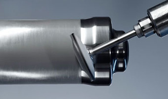
Polishing
From Ra 0.8 to Ra0.1, the polishing process uses abrasive materials to rub the surface of the part, making the surface of the part more shiny, depending on your requirements.
Machining Texture:Smooth, glossy finish
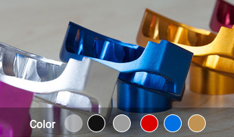
Anodizing
Aluminum and its alloy in the corresponding electrolyte and specific process conditions, due to the action of external current, the process of forming an oxide film on the aluminum product.
Machining Texture:Smooth, matte finish.
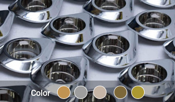
Electroplating
Electroplated coating preserves the surface of parts and resists rusts and other defects from causing decay by applying electric currents to reduce metal cations.
Machining Texture:Smooth, glossy finish.
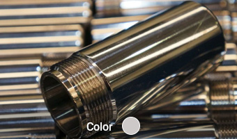
Electroless nickel plating
Electroless nickel plating is a process that deposits an alloy of nickel-phosphorus onto the surface of a metal. This process is chemical only, so does not involve the use of electricity.
Machining Texture:Reduced but visible.
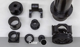
Black oxide
Black oxide is a conversion coating similar to Alodine that is used for steel and stainless steel. It is used mainly for appearance and for mild corrosion resistance..
Machining Texture:Smooth, matte.
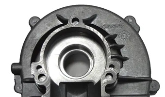
Powder coating
Using corona discharge, we make the powder coating adsorbed to the part, creating a more wear-resistant layer with a typical thickness ranging from 50 μm up to 150 μm.
Machining Texture:Glossy.
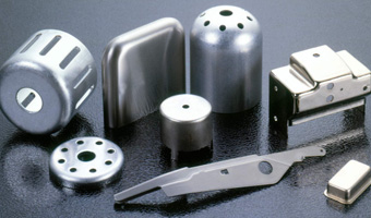
Chromate conversion coating
Chromate conversion coating is a type of conversion coating, used on aluminum as a corrosion inhibitor, as a primer for paint due to increased adherence or to preserve electrical conductivity.
Machining Texture:Visible.
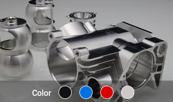
Electrophoresis
In the solution under the action of direct current electric field, the charged resin moves to the opposite electrode phenomenon. Strong corrosion resistance, can be on different colors.
Machining Texture:Visible.
As-machined
The standard finish of our parts, the "machined" finish, has a surface roughness of 3.2 μm (126 μin), which removes sharp edges and cleanly removes burrs from the part.
Machining Texture:There are slight scratches on the visible surface.
Smooth machining
A finishing CNC machining operation can be applied to the part to reduce its surface roughness. The standard smoothing surface roughness is Ra 1.6 μm (64 μin). Light surface scratches are visible.
Machining Texture:Visible, light surface scratches.
Fine machining
Refers to the process of precision treatment of raw materials or semi-finished products. The standard smoothing surface roughness is Ra 0.8 μm (32 μin).
Machining Texture:Slightly visible.
Bead blasting
Bead blasting refers to the use of round spherical media that, when impacted against the surface of a part, will leave a more uniform finish caused by the sphere “dimpling” the surface.
Machining Texture:Frosted grain.
Brushing
Brushing is a surface treatment process that uses abrasive belts to draw traces on the surface of a material, usually for aesthetic purposes.
Polishing
From Ra 0.8 to Ra0.1, the polishing process uses abrasive materials to rub the surface of the part, making the surface of the part more shiny, depending on your requirements.
Machining Texture:Smooth, glossy finish
Anodizing
Aluminum and its alloy in the corresponding electrolyte and specific process conditions, due to the action of external current, the process of forming an oxide film on the aluminum product.
Machining Texture:Smooth, matte finish.
Electroplating
Electroplated coating preserves the surface of parts and resists rusts and other defects from causing decay by applying electric currents to reduce metal cations.
Machining Texture:Smooth, glossy finish.
Electroless nickel plating
Electroless nickel plating is a process that deposits an alloy of nickel-phosphorus onto the surface of a metal. This process is chemical only, so does not involve the use of electricity.
Machining Texture:Reduced but visible.
Black oxide
Black oxide is a conversion coating similar to Alodine that is used for steel and stainless steel. It is used mainly for appearance and for mild corrosion resistance..
Machining Texture:Smooth, matte.
Powder coating
Using corona discharge, we make the powder coating adsorbed to the part, creating a more wear-resistant layer with a typical thickness ranging from 50 μm up to 150 μm.
Machining Texture:Glossy.
Chromate conversion coating
Chromate conversion coating is a type of conversion coating, used on aluminum as a corrosion inhibitor, as a primer for paint due to increased adherence or to preserve electrical conductivity.
Machining Texture:Visible.
Electrophoresis
In the solution under the action of direct current electric field, the charged resin moves to the opposite electrode phenomenon. Strong corrosion resistance, can be on different colors.
Machining Texture:Visible.
Industry
Application Areas of Injection Molding
Our facilities are equipped with the latest in high-precision Injection Molding equipment, capable of executing complex designs with exacting tolerances. From prototyping to full-scale production, It's comprehensive machining capabilities cater to a diverse range of industries, including aerospace, automotive, medical, and more.
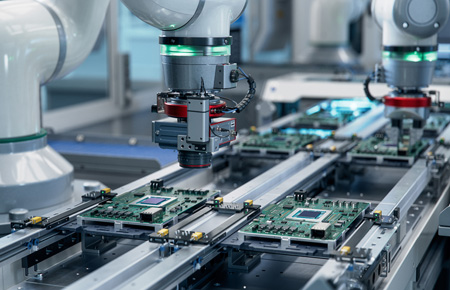
Consumer Electronics
Our manufactured electronic components consistently meet the tight tolerances required in this ever-evolving industry.
Learn More
Aerospace & Aviation
Our manufactured electronic components consistently meet the tight tolerances required in this ever-evolving industry.
Learn More
Automotive
Our manufactured electronic components consistently meet the tight tolerances required in this ever-evolving industry.
Learn More
Medical
Our manufactured electronic components consistently meet the tight tolerances required in this ever-evolving industry.
Learn More
Robotics & Automation
Our manufactured electronic components consistently meet the tight tolerances required in this ever-evolving industry.
Learn More
Industrial Machinery Parts
Our manufactured electronic components consistently meet the tight tolerances required in this ever-evolving industry.
Learn MoreTest Inspection
Quality Assurance at the Heart of Our Operations
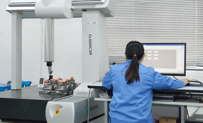
Quality is not just a buzzword at SOMI,it's the foundation upon which we build our reputation Our rigorous quality assurance process encompasses every stage of production, from initial design to final inspection. We employ advanced measurement and testing equipment to verify that each part meets our stringent standards and, more importantly, your expectations. This unwavering dedication to quality ensures that SOMI's Injection Molding services are a step above the rest.
Get a Quote
Contact us Today for Your Injection Molding Requirements
Ready to elevate your manufacturing with the precision and quality of SOMI's Injection Molding services? Contact us today to discuss your project and discover how we can help you achieve unparalleled results. With SOMI, you're not just choosing a service provider, you're choosing a partner dedicated to your success.
We are committed to providing full-process services from prototyping to mass production. We provide rapid prototyping services to ensure that your design can be realized accurately and efficiently.
We hope to discuss potential cooperation opportunities with you and ask you to provide quotation information for your project. Looking forward to your reply and working with you to promote the success of your project!
- *Name
- *Phone
- *Title
- *Content
FAQ
Frequently Asked Questions
If you have any further questions, please contact us. We look forward to working with you.
- What is injection molding?
The short answer
Injection molding is a repeating process that melts thermoplastic pellets in a heated barrel, injects the melt into a closed steel mould under 60 to 150 MPa, holds it under pressure while it shrinks, then cools and ejects the finished part. One cycle takes 15 to 120 seconds, cooling is 50 to 80 percent of that time, and the cycle then repeats automatically.
A machine is three systems
An injection molding machine looks complicated and is conceptually simple. It has three parts, and knowing which one is which is most of what is needed to hold a useful conversation about a part.
- The injection unit. A hopper feeds pellets into a heated barrel containing a reciprocating screw, usually with a length-to-diameter ratio of 18:1 to 24:1. The screw rotates to melt and homogenise the polymer, then slides forward like a plunger to push a measured volume of melt through the nozzle. Barrel temperature is held in three to five zones from the feed throat to the nozzle.
- The clamping unit. This closes the mould, holds it shut against the pressure of the melt and opens it for ejection. Its capacity is quoted in tonnes of clamp force, and machines range from about 5 tonnes for small precision parts to several thousand tonnes for large panels. Insufficient clamp force lets the halves part slightly and resin escapes as flash.
- The mould. A precision cavity in hardened tool steel or aluminium containing the part geometry, runners, gates, cooling channels and ejector pins. The mould, not the machine, determines the part's shape, where it fills, how it cools and how it releases.
One cycle, six stages
Technical references describe the cycle as four stages and as six, and both are correct: the four-stage version groups packing into cooling, while the six-stage version separates them because they are controlled independently.

Six textbook stages, four machine moves, repeated a few thousand times a shift. - Clamping. The moving platen brings the two halves together and the clamp builds to full tonnage. The mould must be completely sealed before injection or the melt will leak at the parting line.
- Injection or filling. The screw moves forward and drives melt through the nozzle, sprue, runner and gate into the cavity. Filling is fast - usually under two seconds - and it determines whether every detail of the cavity is reproduced.
- Packing and holding. Pressure is maintained for 5 to 20 seconds so that additional melt enters the cavity to compensate for shrinkage as the part cools. This stage is what prevents sink marks, internal voids and dimensional drift.
- Cooling. Heat transfers from the part into the mould's cooling channels while the screw rotates and retracts to prepare the next shot. Cooling is 50 to 80 percent of the cycle and it is where part dimensions are effectively set.
- Mould opening. The clamp retracts and separates the halves, exposing the solidified part on the core.
- Ejection. Ejector pins, sleeves or a stripper plate push the part clear. Draft angles on the walls are what make this possible without marking or distorting the part.
Cooling owns the cycle

Cooling is not one step among six; it is most of the clock. The practical consequence of that figure is the single most useful rule in plastic part design: wall thickness drives cost. Solidification time scales roughly with the square of section thickness, so doubling a wall from 1.5 mm to 3 mm multiplies the cooling time by about four. Every additional millimetre of nominal wall, every unnecessary boss and every local thick section adds seconds to every shot for the life of the programme. That is why the standard advice is to keep the wall as thin and as uniform as the function allows and to add ribs where stiffness is needed rather than mass.
The process window
Four conditions determine whether a part comes out right, and they are set independently of the part geometry.

Melt and mould temperature, pressure and cooling time are the four levers a moulder actually tunes. - Melt temperature. Resin dependent, broadly 220 to 300 C for engineering grades and lower for polyolefins. Too cold and the cavity short-shots; too hot and the polymer degrades and loses strength.
- Injection pressure. Typically 60 to 150 MPa, or 600 to 1,500 bar. It has to fill the thinnest wall before the melt freezes without over-packing the area around the gate.
- Mould temperature. 20 to 120 C depending on the resin. Higher mould temperature improves gloss and weld-line strength and reduces residual stress, at the cost of a longer cycle.
- Cooling time. The variable that is genuinely worth optimising, because it is the largest block of cycle time and therefore the largest single driver of unit cost.
Design rules that come from the process
- Keep the wall uniform and in the 1 to 5 mm range. Thick sections cool more slowly than thin ones, which produces sink marks over ribs and bosses and warping across the part.
- Add draft to every wall parallel to the opening direction. About 1 to 3 degrees on smooth surfaces and more on textured ones, because the part shrinks onto the core as it cools.
- Size ribs at 50 to 60 percent of the nominal wall. A rib as thick as the wall behaves like a thick section and sinks on the opposite face.
- Keep radii generous and avoid sharp internal corners. Sharp corners concentrate stress and restrict flow; rounded transitions fill better and are stronger in service.
- Decide the gate and parting line at design stage. Both are mould decisions, and both affect where weld lines, cosmetic blemishes and flash appear. Settling them after the tool is cut is expensive.
What injection molding cannot do
- It cannot mould undercuts for free. Features that block ejection need side actions, lifters or collapsible cores, all of which add tooling cost and cycle time. A snap fit that needs a side action should be checked against an alternative geometry first.
- It cannot be justified at very low volume. Tooling runs from a couple of thousand dollars for a simple aluminium cavity to tens of thousands for a hardened multi-cavity tool, and below a few hundred parts that investment does not return.
- It cannot produce a part that does not fit the machine. Shot size sets the maximum part mass and clamp tonnage sets the maximum projected area; both are hard limits, not preferences.
- It cannot hold tighter than the process allows. Around plus or minus 0.025 to 0.05 mm on features cut into the steel is realistic; anything tighter has to be machined afterwards, which is a different operation and a different cost.
- It cannot use every polymer. Thermoplastics dominate; thermosets need specialised machines because they cross-link and cannot be remelted.
Getting a part quoted
The most useful thing a buyer can send is the model together with the function: what the part does, what it carries, what environment it sees, which surfaces are visible and what it has to mate with. From that we can propose a resin and a wall strategy, flag where draft or a side action will be needed, comment on where weld lines and sink marks are likely to land, and give a tooling price with a unit price at two volumes. See plastic injection molding for the process, aluminium die casting where a metal part is the better answer, and surface finishing for the texture, paint and plating options that follow moulding.
Scope and sources. Cycle stages, clamp force, injection pressure, temperature windows, cooling share and design limits were compiled in 2026 from a four-stage process guide with clamping force and cycle data, a step-by-step process guide listing process parameters and defect causes, a beginner's guide describing machine systems and stage timing and a machine guide covering the injection unit, clamping unit and cycle stages. Ranges vary with resin, part geometry, machine tonnage and mould design, so treat them as typical planning values rather than settings for a specific job. Confirm final parameters on a mould trial and first-article inspection.
- What is the difference between plastic injection molding and 3D printing?
The short answer
Injection molding fills a machined steel cavity with molten resin under 60 to 150 MPa, so it holds plus or minus 0.025 to 0.05 mm, delivers Class A surfaces and keeps 95 to 100 percent of the resin's rated strength. 3D printing builds the part layer by layer with no tooling, holding plus or minus 0.1 to 0.5 mm and retaining 60 to 85 percent of rated strength.
The physical difference comes first
Everything else follows from how the part is formed. Injection molding melts pellets in a heated barrel, injects the melt into a closed steel cavity in under a second or two, holds it under pressure while it shrinks, then cools and ejects it. The polymer is sheared and packed as one continuous mass, so it freezes into a homogeneous part with no internal boundaries. Printing deposits or fuses material in layers, and the bonds between layers are never as strong as the material inside a layer. That single structural difference explains most of the property gap in the comparison below.
The second structural difference is that a mould is a fixed geometry. Once the steel is cut, the part is what it is; the same cavity produces the same part for hundreds of thousands of cycles. A printer is a general-purpose machine that can start a different part on the next build, which is why it is unbeatable for iteration and hopeless for volume.

Eight rows cover almost every question that decides which process fits a part. Tolerance, surface finish and minimum wall

The tolerance gap is roughly an order of magnitude, and it decides whether parts assemble first time. The tolerance difference is the one that causes the most late surprises, because it shows up at assembly rather than at goods-in. A moulded part holds about plus or minus 0.025 to 0.05 mm on features cut into the steel, and the value is repeatable from shot one to shot 500,000. A printed part is typically quoted at plus or minus 0.1 to 0.3 mm for FDM, falling to around plus or minus 0.05 to 0.1 mm for a well-maintained resin process. Where a snap fit, a boss or a port cut-out has to mate with something else, that difference decides how much hand-fitting the assembly line absorbs.
Surface finish follows the tool. A mould can be polished to an SPI A1 mirror or textured to a specific grain, producing Ra 0.4 to 1.6 micrometres and a face that is finished as it leaves the machine. FDM leaves visible layer lines at Ra 6 to 25 micrometres; resin processes are smoother but still need sanding and priming before a paint finish will look like a production part.
The same resin does not give the same part

Printing in the specified resin still does not deliver the specified properties. This is the most commonly misunderstood row in the whole comparison. A buyer who specifies ABS and receives a printed ABS part has not received the same material performance. Printed parts typically retain 60 to 85 percent of the bulk resin's rated tensile strength because the inter-layer bonds are the weak path, and the effect is directional: a part loaded across the build direction can be materially weaker than the same geometry loaded in plane. Moulded parts achieve 95 to 100 percent of the rating because the material is homogeneous. In side-by-side testing of the same geometry in the same ABS grade, the moulded part is consistently stronger in tension than the printed one.
Repeatability, part size and lead time
Repeatability is a quieter difference but a decisive one for anyone buying production rather than prototypes. Moulding routinely demonstrates process capability indices of 1.33 to 2.0 on critical dimensions, which is what allows a plastic part to enter an automotive, medical or appliance supply chain as a controlled component. Printing typically sits at 0.8 to 1.2, which is adequate for fit checks and fixtures but not for a characteristic that has to be statistically capable over a production life.
Part size and lead time pull in opposite directions, which is the part of the trade most often misread. A moulding machine handles parts up to 1,500 mm and beyond, limited only by clamp tonnage; a typical printer bed is around 300 by 300 by 400 mm, and larger parts must be printed in sections and joined. But a printer delivers first parts in hours while a steel tool takes 4 to 8 weeks, so at the start of a program the slower process per part is the faster process to answer.
What you need Choose injection molding Choose 3D printing Quantity 1,000 pieces and upward, to millions 1 to about 1,000 pieces Tolerance that matters Mating features, bearings, seals Fit checks and non-critical envelopes Appearance Visible Class A or textured surfaces Hidden or painted-over surfaces Material performance The datasheet value has to be met Rough property parity is enough Geometry Can be demoulded with draft and a parting line Internal channels, lattices, no draft Change frequency The design is frozen The design is still moving Schedule Launch date is months away First parts needed this week Which process for which stage of the program
The two processes are not competitors so much as consecutive stages, and the friction usually comes from skipping a stage rather than from choosing the wrong one.
- Concept and fit. Print in an inexpensive resin to check form, feel and packaging. Nothing is frozen and change costs nothing.
- Formal validation. Print in the intended resin family, or a close relative, to test function and assembly. Tolerances are provisional, so build in adjustment.
- Pre-production. Either cut a single-cavity aluminium tool, which gives real process capability in 2 to 4 weeks, or run a bridge tool while the production mould is being made.
- Production. Move to a hardened multi-cavity tool once volumes and the design justify it. This is where the unit price collapses and where the tolerance, finish and repeatability advantages finally pay.
Where 3D printing stays the better answer
- Genuinely low volumes. Below a few hundred parts, tooling cannot be amortised and printing wins outright on total spend.
- Geometry a mould cannot open. Internal cooling channels, lattice infill and organic shapes with no parting line are additive-only designs.
- Late customisation. Where each unit is different, a tool is the wrong answer by definition; patient-specific medical devices and custom fixtures belong in printing.
- Spares and obsolescence. Printing a spare on demand removes the inventory and the tooling question entirely.
- Speed at the start. A part in hand this week is worth more than a cheaper part in ten weeks when the program has not yet been released.
Getting the right process for your part
The question is rarely which process is better in general, but which is right for this geometry at this volume with this tolerance. Send the model or drawing with the annual volume, the features that must mate with something else, the surfaces that will be seen and the properties the part actually has to meet. We mould engineering resins and quote the additive equivalents beside them, so the comparison can be made on your part rather than on a general table. See plastic injection molding for the production route, SLA 3D printing for fine detail and smooth surfaces, and SLS 3D printing for functional nylon prototypes.
Scope and sources. Tolerance bands, surface roughness, minimum wall, strength retention, capability indices and size limits were compiled in 2026 from a process comparison that measures tensile retention and Cpk for both routes, a factor-by-factor comparison of moulding and printing with tolerance and finish values, a cost and capability guide covering lead times, tolerances and material trade-offs and a plastic injection molding process guide covering design limits and mould design. Capability depends on part geometry, gate and cooling design, machine condition and build orientation, so treat every band here as typical planning data rather than a specification. Confirm tolerances on a first-article inspection and, for printed parts, on parts from more than one build.
- What is the main advantage of plastic injection molding over additive manufacturing?
The short answer
The main advantage is unit cost at volume. Injection molding needs a mold costing USD 2,000 to 40,000 and takes 2 to 8 weeks to build, but then a part costs USD 0.10 to 2.00 and leaves the machine every 15 to 60 seconds. Additive manufacturing has no tooling but a part price of USD 1 to 40.
One number carries the whole argument
Every other difference between the two processes is downstream of a single fact: injection molding produces a part in seconds and additive manufacturing produces one in hours. Molding pushes molten resin into a steel cavity at 60 to 150 MPa and the part is solid within 15 to 60 seconds. A printer deposits or fuses material layer by layer, so the same part takes 30 minutes to 12 hours, and that time is what the customer pays for. A moulding cell runs 500 to 5,000 parts an hour once the tool is qualified; a print farm scales only by buying more printers.
That is why the per-part price of a moulded component falls year on year as the tool amortises, while the per-part price of a printed component stays almost flat whether you order 50 or 5,000. The two cost curves are shaped differently, and the crossover between them is the only decision that really matters.
Where the money actually goes
It helps to separate the four cost lines, because three of them behave in opposite directions.

Tooling is the only line that rises. Everything else falls or disappears at volume. - Tooling. A prototype aluminium tool can start near USD 1,500 to 4,000 for a simple single-cavity part. Production tooling in hardened steel with multiple cavities, hot runners and optimised cooling runs USD 8,000 to 40,000, and multi-shot or over-moulded tools reach USD 60,000 to 150,000. Lead time is 2 to 4 weeks for aluminium and 4 to 8 weeks for hardened steel.
- Material. This is where the gap is widest and least discussed. Moulding compound is bought as pellets by the tonne. Filament, resin and powder for additive processes cost roughly 8 to 15 times more per kilogram for comparable engineering polymers, and support material is additional waste.
- Cycle time. At 15 to 60 seconds per shot, one machine produces tens of thousands of parts a week. A printer needs days of continuous running for the same quantity, and someone has to load, unload and post-process each batch.
- Secondary operations. A well-designed moulding usually needs none. A printed part almost always needs support removal, and often sanding, filling, priming or dyeing before it looks like a product.
Material cost is where the gap is widest
Buyers comparing quotations often attribute the price difference to tooling alone, and they are wrong by a wide margin. Tooling is a one-time figure that is divided by the annual volume. Material is a recurring figure that is paid on every single part. When the feedstock costs 8 to 15 times as much per kilogram and a meaningful share of it becomes support structure or failed builds, the material line alone can exceed the entire moulded part price. That is why the crossover arrives earlier than most first-time buyers expect on parts with real mass in them, and later than expected on thin, low-mass parts where the print uses very little material.
Where the gap shows up in real numbers

At 10,000 pieces the moulded part is roughly ten times cheaper, and the gap widens with volume. Factor Injection molding Additive manufacturing Upfront tooling USD 2,000 to 40,000, more for multi-shot None Tooling lead time 2 to 4 weeks aluminium, 4 to 8 weeks steel Hours to days Unit cost at 1,000 USD 2 to 10, tooling still being absorbed USD 10 to 35 Unit cost at 10,000 USD 0.30 to 2.00 USD 5 to 40, unchanged Unit cost at 100,000 USD 0.05 to 1.00 Still unchanged Cycle time per part 15 to 60 seconds 30 minutes to over 12 hours Material price per kg Baseline 8 to 15 times higher Scrap rate Under 1 percent on a stable mould Build failures and support waste Design change cost Tooling modification or a new insert Effectively free How to calculate your own break-even
The arithmetic is simple enough to do before requesting a quotation, and it is worth doing because the answer changes the conversation.
- Get the printed part price. Ask for a quote at the real quantity, not a sample price. Add support removal and any finishing you would actually need.
- Estimate the moulded part price. A supplier can quote a per-part price for the volume band you expect, with tooling shown separately.
- Subtract, then divide. Break-even quantity equals tooling cost divided by the difference between the two unit prices. An USD 8,000 tool against a USD 4.00 printed part and a USD 0.50 moulded part gives 8,000 divided by 3.50, or about 2,300 pieces.
- Check the tooling against the program. If the expected lifetime volume is below the break-even, the tool never pays for itself. If it is three or four times the break-even, the tooling decision is already made.

Simple small parts cross over at a few hundred pieces; complex ones need a few thousand. Two adjustments are worth making to the raw result. First, add shipping, packaging and inventory carry to the printed side, because printed parts are usually ordered in small batches and shipped as such. Second, treat the break-even as a range rather than a point, because it moves with part mass, cavity count and the finishing requirement.
Where additive manufacturing still wins, and should
- Anything before the design is frozen. A printed prototype that exposes a design error costs a fraction of a mould that has to be modified or replaced. During development the cheapest process is the one that lets you change your mind.
- Volumes under a few hundred. Spare parts programs, clinical trials, custom fixtures and trade-show units rarely justify a tool, and a print holds no inventory.
- Geometry a mould cannot open. Internal channels, lattices and organic load paths with no parting line are the clear case where a printer is not a compromise but the only route.
- Bridge production. While a tool is being cut, printed parts can supply early builds and testing so that a launch is not delayed by tooling lead time.
Getting a costed comparison rather than a rule of thumb
A useful quotation shows the break-even instead of asserting a volume. Send the part or the STEP file with the annual volume and expected program life, the resin family or the performance requirement, the cosmetic surfaces, and any tolerance that matters to assembly. We mould engineering resins and can set the print alternatives beside the moulded price at two or three volumes so that the tooling decision is visible on the page. See plastic injection molding for the process and its design rules, FDM 3D printing and SLS 3D printing for the additive routes we quote alongside it.
Scope and sources. Tooling ranges, unit prices, cycle times, material price ratios and break-even figures were compiled in 2026 from a comparison guide with 2026 tooling prices and a worked break-even formula, a process comparison covering cost crossover points by part complexity, a small-batch cost study that tabulates total spend from 100 to 10,000 pieces and a volume-based cost table for injection molding against printing. Prices move with region, resin, part mass, cavity count and finishing, so the figures here are planning bands for budgeting rather than quotations. Confirm against a DFM review and a firm quotation at your real annual volume before committing to tooling.
Explore More
SOMI Manufacturing Capabilities


From concept to product
From prototyping to production, our production sites can handle all your manufacturing projects.
subscription