


What Role Does an F Type Connector Supplier Play in 75 Ohm and 50 Ohm Systems?
In the intricate world of radio frequency (RF) systems, where clear and efficient signal transmission is paramount, choosing the right components is a critical decision. Among these, the RF connector stands as a lynchpin, ensuring the seamless flow of signals with minimal loss or interference. The F-Type connector, in particular, plays a significant and often underestimated role, especially within the ubiquitous 75 Ohm systems that power our daily lives.
The landscape of coaxial cables and connectors is defined by impedance—a fundamental property that dictates system performance. Whether dealing with 50 Ohm or 75 Ohm setups, this electrical characteristic must be precisely matched to prevent signal degradation. This is where the expertise of a professional F-Type connector supplier becomes invaluable. They are the unsung heroes who guide engineers and technicians in making the correct choices, ensuring that everything from our home entertainment systems to critical broadcasting infrastructure is connected with reliability and precision. As integral components in countless applications, RF connectors like the F-Type demand careful selection, and a knowledgeable supplier is the key to unlocking optimal system performance.
The Foundation of Connectivity: How a Savvy F Type Connector Supplier Guides Initial Selection
A proficient F-Type connector supplier does more than just provide a part; they serve as a foundational partner in the design and implementation of any RF system. Their guidance during the initial selection phase is crucial for establishing a connection that is both reliable and optimized for the specific application. This expertise ensures that from the very first component, the system is built for success.
Understanding Diverse RF Connector Types and Their Frequency Limits
The world of RF connectors is vast, with dozens of types designed for specific needs, each characterized by key parameters like physical size, power handling, and, most importantly, frequency range. The maximum frequency a connector can handle without significant signal loss is a primary filter in the selection process. Operating a connector above its rated frequency can lead to poor electrical performance and signal degradation.
Common RF connectors and their typical frequency limits include:
- UHF Connectors: Often used in amateur radio, these are suitable for low-frequency applications, generally below 100 MHz.
- BNC (Bayonet Ne'er-Concelman): Widely used in test equipment and video, these quick-connect/disconnect connectors are reliable for frequencies up to 4 GHz.
- SMA (SubMiniature version A): These compact, threaded connectors are a favorite among RF engineers for their reliable performance up to 18 GHz, making them suitable for everything from Wi-Fi antennas to microwave systems.
- N-Type: Known for their rugged, weatherproof design, N-Type connectors are a staple in telecommunications and can handle frequencies up to 11 GHz, with precision versions reaching 18 GHz.
- High-Frequency Connectors (2.92mm, 2.4mm, 1.85mm): With the advent of 5G and millimeter-wave technologies, connectors like the 2.92mm (up to 40 GHz) and 1.85mm (up to 65 GHz) have become essential for advanced testing, radar, and aerospace systems.
A knowledgeable supplier helps navigate this complex landscape, ensuring the chosen connector's frequency range comfortably exceeds the system's maximum operating frequency to guarantee signal integrity.

Comparing F-Type and Other Common Connectors
While many connectors exist, the F-Type connector holds a unique position, particularly in consumer electronics. Developed in the 1950s for the burgeoning cable television market, its design was optimized for cost-effectiveness and ease of use in 75 Ohm systems.
Here's a comparison of the F-Type connector with other prevalent RF connectors:
| Feature | F-Type Connector | N-Type Connector | BNC Connector | SMA Connector |
|---|---|---|---|---|
| Primary Impedance | 75 Ohm. | 50 Ohm. | 50 Ohm / 75 Ohm. | 50 Ohm. |
| Coupling Mechanism | Threaded (3/8-32 thread). | Threaded, robust. | Bayonet lock (quick connect/disconnect). | Threaded, compact. |
| Frequency Range | Up to 3 GHz, some variations higher. | Up to 11 GHz (standard), 18 GHz (precision). | Up to 4 GHz. | Up to 18 GHz (standard), higher for precision. |
| Center Pin | Uses the cable's solid center conductor. | Separate, captive pin. | Separate, captive pin. | Separate, captive pin. |
| Common Applications | Cable TV (CATV), satellite TV, cable modems, consumer video. | Antennas, base stations, high-power applications, test equipment. | Test equipment, professional video, amateur radio. | Wi-Fi, microwave systems, GPS, high-frequency circuits. |
| Key Advantages | Extremely low cost, simple installation. | High power handling, weatherproof, durable. | Fast mating cycle. | Excellent high-frequency performance, compact size. |
| Key Disadvantages | Less durable, not ideal for repeated mating cycles, lower weather resistance. | Larger size, more expensive. | Poor performance at higher microwave frequencies. | Smaller size can make it delicate. |
The F-Type's most distinctive feature is its use of the coaxial cable's own center conductor as the signal pin. This simplifies the design, reduces manufacturing costs dramatically, and makes field installation with basic tools very straightforward. However, this design also makes it less robust compared to connectors like the N-Type or BNC, which use a dedicated, more durable internal pin. A supplier's role is to help weigh these trade-offs. For a high-volume consumer product like a set-top box, the F-Type's cost-effectiveness is a major benefit. For a piece of lab equipment requiring thousands of mating cycles, a BNC or SMA connector would be a more appropriate choice.
The Critical Match: Why Physical Dimensions Matter for Optimal Signal from Your F Type Connector Supplier
In the realm of high-frequency signals, precision is everything. The physical dimensions of a coaxial connector are not arbitrary; they are meticulously engineered to maintain the cable's characteristic impedance and ensure a seamless path for the signal. Any deviation in these dimensions can create an impedance mismatch, leading to signal reflections, insertion loss, and overall degradation of signal integrity.
The core principle lies in the geometry of the coaxial structure. The characteristic impedance is a function of the ratio of the outer conductor's inner diameter to the inner conductor's outer diameter, as well as the dielectric constant of the material separating them. Even minute variations in these dimensions can disrupt this delicate balance.
Key physical aspects where a supplier's quality control is paramount include:
- Conductor Diameters: The diameter of the center conductor (or the pin in the female jack) and the inner diameter of the shield must be manufactured to tight tolerances. In an F-Type connector, where the cable's center wire itself is the pin, the compatibility between the connector and the specific cable gauge (e.g., RG-6, RG-59) is crucial. A supplier ensures their connectors are precisely matched to standard cable dimensions.
- Dielectric Consistency: The insulating material (dielectric) that separates the center conductor from the shield must be uniform in both its material properties and its dimensions. Inconsistencies can cause localized changes in impedance.
- Mating Interface: The point where two connectors meet is a critical transition. High-quality connectors are designed to ensure the male pin and female socket align perfectly, with minimal gaps and a secure physical connection to prevent signal leakage or reflections. The precision of the 3/8-32 UNEF thread on an F-Type connector, for example, determines how securely it mates, which impacts stability.
A reputable F-Type connector supplier sources or manufactures parts with exceptional precision. They understand that while an F-Type is a low-cost connector, manufacturing it to tight tolerances is non-negotiable for high-frequency applications like modern cable internet and high-definition satellite TV. Adhering to these tight tolerances ensures that each component fits together perfectly, which is essential for maintaining a dependable and high-quality finished product.
Navigating the World of Ohms: An F Type Connector Supplier's Expertise in 50 Ohm vs. 75 Ohm Systems
The concepts of 50 Ohm and 75 Ohm are central to the world of RF engineering, and understanding their differences is fundamental to designing a functional system. An expert F-Type connector supplier possesses deep knowledge in this area, guiding clients away from costly mismatches and toward an optimized, efficient signal path. Their role is to ensure the impedance of the connector, cable, and components are all in perfect harmony.
Demystifying Impedance: Balancing Power and Attenuation
Impedance, measured in Ohms (Ω), is the total opposition a circuit presents to an alternating current at a given frequency. In RF systems, which rely on transmission lines like coaxial cables, impedance is a critical characteristic. For maximum power transfer and minimal signal reflection, the impedance of the source (e.g., a transmitter), the load (e.g., an antenna or receiver), and the interconnecting cable and connectors must all match.
When impedances are mismatched, a portion of the signal's energy is reflected back toward the source instead of continuing to the load. This creates several problems:
- Signal Loss: The reflected energy is effectively lost, reducing the power that reaches the destination. This is measured by parameters like Voltage Standing Wave Ratio (VSWR) and return loss.
- Distortion: Reflected signals can interfere with the primary signal, causing distortion, ghosting in analog video, or increased bit error rates in digital data.
- Component Damage: In high-power transmitting systems, reflected power can return to the transmitter's amplifier, potentially causing it to overheat and fail.
The choice between the two dominant standards, 50 Ohm and 75 Ohm, is a classic engineering trade-off. It's a balance between two key factors:
- Power Handling: The ability to transmit high power without breakdown. Research at Bell Labs in the 1920s determined that maximum power handling for coaxial cables is achieved at an impedance of around 30 Ohms.
- Signal Attenuation: The loss of signal strength over a given distance. The same research found that the point of lowest signal loss (attenuation) occurs at an impedance of approximately 77 Ohms.
Neither 30 nor 77 Ohms became the universal standard. Instead, a compromise was struck. A knowledgeable supplier understands this history and can explain that the choice is not arbitrary but deeply rooted in the physics of signal transmission.

The 50 Ohm Standard: Powering Most Communication Systems
The 50 Ohm standard is the backbone of the vast majority of RF and microwave systems. This impedance was chosen as a practical "golden compromise" between the optimal points for power handling (around 30 Ohms) and minimum signal loss (around 77 Ohms) in early air-dielectric coaxial cables.
The key reasons for the prevalence of 50 Ohm systems include:
- Best Compromise for Performance: 50 Ohms strikes an excellent balance, allowing for reasonably high power transmission while keeping signal attenuation acceptably low. This makes it a versatile choice for systems that both transmit and receive signals.
- Global Standardization: The establishment of 50 Ohms as a standard after World War II ensured compatibility across components from different manufacturers. This global norm means that most RF components, test equipment like oscilloscopes and network analyzers, and connectors are designed with an internal 50 Ohm match.
- Wide Range of Applications: Because of its balanced characteristics, 50 Ohm coaxial cable is the default for a huge array of applications, including:
- Two-way radio communications (e.g., walkie-talkies, cellular base stations).
- Wireless data networks (Wi-Fi routers and antennas).
- RF test and measurement equipment.
- GPS systems.
- High-frequency data links.
Connectors designed for 50 Ohm systems, such as the N-Type, SMA, and BNC (50 Ohm version), are built to maintain this impedance precisely. A supplier's expertise is critical in ensuring a client doesn't inadvertently use a 75 Ohm component in a 50 Ohm chain, which would create a mismatch and degrade system performance.
The 75 Ohm Standard and the F-Type Connector: The CATV Connection
While 50 Ohm systems dominate the world of RF transmission and data communications, 75 Ohm is the undisputed king of video and television. The reason for this is simple: TV and cable systems are primarily concerned with receiving signals, often over long distances, making low signal loss (attenuation) the most critical factor. As established, coaxial cable impedance for minimum attenuation is around 77 Ohms, making 75 Ohms the practical and standardized choice.
This is the world where the F-Type connector was born and continues to reign supreme. Its entire design philosophy is built around the needs of the 75 Ohm ecosystem.
Key Applications for 75 Ohm Systems and F-Type Connectors:
- Cable Television (CATV): This is the original and most widespread application. F-Type connectors are used on all the coaxial cables (typically RG-6 or the older RG-59) that bring cable TV signals into homes and connect to set-top boxes.
- Satellite Television: The signal from a satellite dish LNB (Low-Noise Block downconverter) is sent to the satellite receiver via a 75 Ohm coaxial cable terminated with F-Type connectors.
- Broadband Internet: Cable internet services (DOCSIS) deliver high-speed data over the same 75 Ohm coaxial infrastructure as cable TV, using F-Type connectors to link the wall outlet to the cable modem.
- Over-the-Air (OTA) Antennas: Rooftop and indoor antennas that pick up local broadcast signals use 75 Ohm cable and F-Type connectors to feed the signal to a television or digital tuner.
- CCTV and Surveillance Systems: While some professional systems use 75 Ohm BNC connectors, many home and small business CCTV systems utilize the cost-effective F-Type connector.
An F-Type connector supplier is an expert in this domain. They understand that for these applications, power handling is not a major concern, but preserving the integrity of a weak signal coming from an antenna or over a long cable run is paramount. They provide connectors specifically designed for common 75 Ohm cables like RG-6 and RG-11, ensuring the impedance match is perfect and signal loss is kept to an absolute minimum. Using a 50 Ohm connector in these systems would create a significant impedance mismatch, leading to reflected signals and a potential 4% or more loss of signal power, which can manifest as a pixelated picture or an unstable internet connection.
Beyond the Spec Sheet: Attachment Methods and Performance Parameters from an Expert F Type Connector Supplier
Choosing the right connector involves more than just matching impedance and frequency. The physical construction, how it attaches to the cable, and its certified performance under various conditions are just as crucial for long-term reliability. An expert F-Type connector supplier provides insight into these details that go far beyond the basic spec sheet, ensuring the connection is secure, durable, and performs as expected in the real world.
Secure Connections: Exploring RF Connector Attachment Methods
Terminating a coaxial cable with a connector is a precise process that permanently joins the two components. The method used to attach the connector to the cable directly influences the connection's mechanical strength and electrical integrity. For F-Type connectors, there are three primary attachment methods, each with distinct advantages and use cases.
Twist-On:
- Description: This is the simplest method, requiring no special tools. After the cable is stripped, the connector is simply twisted onto the outer jacket, with internal threads cutting into the plastic to create a grip.
- Use Case: Best suited for quick, temporary, or DIY field repairs where professional tools are unavailable. They are often reusable.
- Drawback: Twist-on connectors provide the least secure connection and are more susceptible to being pulled off or allowing signal leakage, making them unsuitable for professional or high-reliability installations.
Crimp-On:
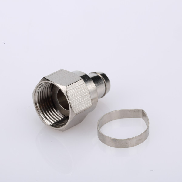
- Description: This method involves sliding a metal ring, called a ferrule, over the cable jacket. After the connector body is placed on the prepared cable end, a specialized crimping tool is used to compress the ferrule around the jacket and connector base, creating a secure mechanical bond.
- Use Case: This was the industry standard for many years, offering a much more reliable connection than the twist-on method. It's still used in many applications where a durable connection is needed.
- Drawback: Requires a specific crimping tool and die for the connector and cable size. Once crimped, the connector is not reusable.
Compression:
- Description: This is the modern, professional standard for F-Type connectors. A compression connector has an integrated sleeve. After the connector is pushed onto the stripped cable, a compression tool is used to uniformly collapse the sleeve, creating a 360-degree bond between the connector and the cable.
- Use Case: Preferred by cable TV and satellite installers for permanent installations. This method creates a robust, weatherproof, and electrically superior connection.
- Drawback: Requires a dedicated compression tool. Like crimp-on connectors, they are a one-time use attachment.
An expert supplier can guide a user to the correct method for their application, explaining the trade-offs between ease of installation, cost, and long-term reliability. For any permanent or critical system, they will almost always recommend compression connectors for their superior seal and strength.
The Impact of Crimping, Clamping, and Soldering on Reliability
The reliability of a termination is a function of its mechanical strength and its electrical consistency. Each attachment method—crimping, soldering, and clamping (a category that includes compression)—offers a different balance of these attributes. A skilled F-Type connector supplier can articulate these differences clearly.
Soldering:
- Reliability: A properly soldered connection provides an excellent, continuous electrical path with very low resistance. It forms a strong metallurgical bond.
- Impact: For high-frequency applications, a well-executed solder joint on the center pin (where applicable, not on standard F-Types) can offer superior performance by minimizing impedance discontinuities. However, a "cold" or poorly flowed solder joint can be brittle, increase resistance, and become a point of failure. The heat required can also damage the cable's dielectric if not applied carefully by a skilled technician.
Crimping (including Compression):
- Reliability: A modern compression crimp is considered the most reliable method for F-Type connectors in field applications. When performed with the correct tools, the crimp creates a "cold weld," a gas-tight seal that is mechanically robust and highly resistant to vibration and environmental factors like moisture.
- Impact: The key to a reliable crimp is consistency. Using a high-quality, calibrated tool ensures that every connection is identical, repeatable, and meets performance specifications. This method is faster and less skill-dependent than soldering, which is why it's preferred by professionals for high-volume installations. A poor crimp, however, can be worse than a poor solder joint, as it may be mechanically loose and create an intermittent electrical connection.
Clamping (Screw-Terminals):
- Reliability: This method is less common for F-Type connectors but is used in some other RF types. It relies on a screw to clamp the conductor in place. Its reliability is highly dependent on the correct torque and the mechanical design. It can loosen over time with vibration.
- Impact: While easy to install and adjust, clamp-style connections are generally considered less reliable than crimp or solder for long-term or harsh-environment applications.
The following table summarizes the reliability trade-offs:
| Attachment Method | Mechanical Strength | Electrical Consistency | Resistance to Vibration | Skill/Tool Requirement |
|---|---|---|---|---|
| Soldering | Good to Excellent | High (if done well) | Fair (can be brittle) | High skill, soldering iron |
| Crimping | Very Good | Excellent (with proper tool) | Excellent | Low-to-moderate skill, specific crimp tool |
| Compression | Excellent | Excellent | Excellent | Low skill, specific compression tool |
Ultimately, for F-Type connectors, compression is the gold standard for reliability. A supplier adds value by offering not just the connectors but also the certified tools that guarantee a perfect termination every time, ensuring the connection is secure, weatherproof, and electrically transparent.
Electrical Performance: What an F Type Connector Supplier Guarantees for Your System
Beyond the physical object, what a customer is truly buying from an F-Type connector supplier is a guarantee of electrical performance. These guarantees are quantified by several key parameters that describe how well the connector preserves the signal passing through it. A reputable supplier provides datasheets with clear specifications for these metrics, ensuring their products meet the demands of modern RF systems.
Key Electrical Performance Parameters:
Voltage Standing Wave Ratio (VSWR) and Return Loss: These two parameters measure the same phenomenon: signal reflection due to impedance mismatch.
- VSWR is a ratio that quantifies the efficiency of power transfer. A perfect match is a VSWR of 1:1 (no reflection). Higher numbers indicate a worse match. For general applications, a VSWR below 1.5:1 is considered good.
- Return Loss measures the amount of power that is reflected back toward the source, expressed in decibels (dB). A higher return loss value is better, as it means less power is being reflected. A return loss of 20 dB, for example, means that only 1% of the signal power is reflected. A high-quality F-Type connector will have a high return loss (and therefore a low VSWR) across its specified frequency range.
Insertion Loss: This parameter measures the amount of signal power lost as it travels through the connector itself. All connectors introduce some loss due to the resistance of their conductive materials and imperfections in the dielectric. This loss is expressed in dB and increases with frequency. An F-Type connector supplier will guarantee a maximum insertion loss, often a value as low as 0.2 or 0.3 dB at 1 GHz, ensuring the connector is nearly "transparent" to the signal.
RF Leakage (Shielding Effectiveness): This specifies how well the connector's body shields the signal from outside interference and prevents the signal from leaking out. It is measured in dB, with a more negative number indicating better shielding. A quality F-Type connector might specify RF leakage of -100 dB at 1 GHz, which is crucial for preventing stray signals from degrading performance, especially in environments with many wireless devices.
Passive Intermodulation (PIM): PIM is a form of interference generated when two or more signals mix in a passive device with non-linear properties, such as a poorly made or corroded connector. This creates unwanted new frequencies that can fall into a system's receive band, raising the noise floor and degrading performance. While a bigger concern in high-power cellular systems, low-PIM design is still a mark of quality. Suppliers ensure this by using high-quality, non-ferromagnetic materials and precise manufacturing to avoid the "rusty bolt effect" that causes PIM.
By guaranteeing these specifications, an F-Type connector supplier provides confidence that their components will not be the weak link in the RF signal chain. They ensure that the maximum amount of signal power reaches its destination with minimal reflection, loss, or distortion.
Mechanical and Environmental Resilience: Durability from an F Type Connector Supplier
An RF system is often only as strong as its most vulnerable physical component. For connectors used in demanding or outdoor environments, mechanical and environmental resilience is not a luxury—it is a necessity. A quality F-Type connector supplier provides products that guarantee long-term durability, ensuring the connection remains stable despite physical stress and environmental exposure.
Mechanical Durability:
- Mating Cycles: This specification indicates how many times a connector can be mated and unmated before its performance degrades due to wear on the plating and mechanical parts. While a standard F-Type connector might be rated for 100-500 mating cycles, this is more than sufficient for its typical application in permanent or semi-permanent installations like home entertainment systems.
- Vibration Resistance: The threaded coupling mechanism of an F-Type connector provides an inherently secure and vibration-resistant connection when properly torqued. This prevents the connector from loosening over time, which would cause signal degradation. Suppliers who cater to industrial or automotive applications may offer connectors with enhanced locking features.
- Material Strength: The choice of materials for the connector body and plating is crucial for durability. Nickel-plated brass is common for F-Type connectors, offering a good balance of strength, corrosion resistance, and cost. High-quality manufacturing ensures the connector can withstand the physical stress of installation and use without deformation.
Environmental Resilience:
- Operating Temperature Range: Connectors are rated to perform reliably within a specific temperature range, for example, from -40°C to +85°C. This ensures that the materials do not become brittle in the cold or deform in the heat, which would compromise the connection's integrity.
- Moisture and Dust Resistance (IP Rating): Standard F-Type connectors are not inherently weatherproof. However, for outdoor applications like satellite dish or antenna installations, suppliers offer weatherproof versions. These often include O-rings inside the nut to create a tight seal at the mating point and are designed for use with compression fittings that provide a watertight barrier around the cable. For harsh environments, connectors with a specific Ingress Protection (IP) rating, such as IP67 (dust-tight and protected against temporary water immersion) or IP68 (protected against continuous immersion), are available.
- Corrosion Resistance: For outdoor or industrial use, resistance to corrosion from salt spray, humidity, and atmospheric pollutants is vital. Higher-quality plating, such as nickel or gold on the contacts, prevents oxidation that would otherwise increase contact resistance and degrade the signal over time. Suppliers adhering to military standards like MIL-STD-202 will have their connectors rigorously tested against factors like salt atmosphere, moisture, and thermal shock.
By providing connectors with certified mechanical and environmental specifications, a supplier gives engineers and installers the confidence that the connection will remain robust and reliable for the entire service life of the system, even in challenging conditions.
Conclusion
Ultimately, the success and longevity of your RF system hinge on making smart choices, especially when it comes to critical components like connectors. We've seen how various factors, from frequency limits and impedance matching to attachment methods and material durability, play a pivotal role in overall performance. A seemingly simple part can be the difference between a crystal-clear signal and a system plagued by loss and interference.
Whether you are operating within a 50 Ohm communication network or a 75 Ohm CATV system, a knowledgeable F-Type connector supplier is an indispensable partner. They bring the expertise needed to navigate complex specifications and ensure your setup performs optimally, reliably, and efficiently for years to come. Their guidance transforms a simple component purchase into a strategic investment in your system's integrity.
Remember, for all your custom CNC Turning Parts needs, including specialized connectors and precision-manufactured components, reliable OEM and ODM services are dedicated to delivering manufacturing excellence. Don't hesitate to seek expert advice to ensure every connection in your system is a strong one. We hope this guide has been informative. Please feel free to share it with your colleagues and leave your thoughts or questions in the comments below

