Every machined assembly depends on threads: a single poorly designed tapped hole can break a tap, scrap an expensive part, or fail in the field. In 2026, with the global CNC machine tool market estimated between USD 109 billion and USD 129 billion and fastener-intensive industries like automotive, aerospace and medical devices scaling production, getting thread design right is a competitive necessity rather than a detail. This guide explains how threads and tapped holes are actually machined, which design rules and tolerance classes to specify, and how to avoid the mistakes that drive up cost and rejection rates.

What Are Threads and Tapped Holes in CNC Machining?
Threads are helical grooves cut or formed on a surface. External threads (on bolts and shafts) and internal threads (inside holes) work together to create a detachable, load-bearing joint. A tapped hole is an internal thread produced with a tap, while a clearance hole is simply drilled to let a fastener pass through without engaging. Understanding the distinction matters because each feature has different tolerances, tooling and inspection requirements.
The three critical thread dimensions are the major diameter (outermost width), the pitch (distance between adjacent crests), and the pitch diameter (the imaginary cylinder where thread width equals space width — the dimension actually controlled by tolerance classes and measured by thread gauges). Designers specify all three, together with thread depth and position, on drawings or in 3D model PMI annotations.
Key Benefits of Getting Thread Design Right
Threaded features are among the most common — and most failure-prone — elements in CNC machined parts. Designing them correctly pays off across cost, quality and delivery:
- Reliable assemblies. Correct engagement depth (typically 1.0–1.5 times the thread diameter) ensures the bolt yields before the thread strips, preventing premature joint failure.
- Lower manufacturing cost. On parts with 30 or more holes, tapping can consume 20–40% of total cycle time; standard sizes, through holes and moderate depths keep that share under control.
- Fewer rejections. Process-controlled CNC threading reduces thread-related non-conformances by 60–80% compared with manual methods, according to quality management research cited in 2026 threading guides.
- Full traceability. ISO 9001:2015 certified shops document every threading operation, providing the audit trails that medical and automotive customers require.
Put simply: a few minutes spent on thread specification at the design stage avoids hours of rework and scrapped parts on the shop floor.
Thread Standards and Tolerance Classes
Thread standards define the geometry, while tolerance classes define how tight or loose the fit is. Two systems dominate global sourcing: ISO metric threads (ISO 261 / ISO 965) and Unified threads (ASME B1.1). A complete callout such as M8 × 1.25 – 6H or 1/4-20 UNC – 2B leaves no ambiguity for the machinist.
| Standard | System | Default class | When to use it |
|---|
| ISO 965 (metric) | M6 × 1 – 6H | 6H | Standard industrial fit — the correct default for general assemblies |
| ISO 965 (metric) | M6 × 1 – 5H | 5H (tighter) | High-volume interchangeability and precision applications |
| ASME B1.1 (Unified) | 1/4-20 UNC – 2B | 2B | Standard commercial fit — most common North American default |
| ASME B1.1 (Unified) | 1/4-20 UNC – 3B | 3B (precision) | Critical joints needing tighter pitch-diameter control |
Mixing metric and Unified threads in the same assembly is one of the most frequent specification mistakes. Also remember that for blind holes the drawing must show both the full-thread depth and the drill depth — they are different numbers, and confusing them is a classic cause of broken taps and incomplete threads.

Design Guidelines: Thread Depth, Engagement and Blind Hole Clearance
Thread engagement is the functional length of usable thread. Most of the load on a fastener concentrates on the first few threads, so extending engagement beyond about 1.5 times the major diameter adds machining time and tap-breakage risk without meaningful strength gain.
| Material / scenario | Recommended engagement | Notes |
|---|
| Aluminum (structural minimum) | 1.5D | Aluminum has lower shear strength; more engaged threads needed |
| Carbon steel (e.g., AISI 1018) | 1.0–1.5D | 1.0D is structurally adequate for most bolt-loaded joints |
| Stainless steel 316L | 1.0–1.5D | Beyond 1.5D is a high-risk zone for tap breakage in deep blind holes |
| High-load or critical applications | Up to 2.0D | Only where load analysis justifies the extra machining cost |
Three rules keep tapped holes manufacturable:
- Specify thread depth, not drill depth. For blind holes, the drill depth must exceed the full-thread depth by at least 1–1.5 thread pitches to give the tap clearance and room for chips. A common stack for an M10 × 1.5 blind tapped hole in aluminum is 15 mm thread engagement, 8.5 mm tap drill, and 20–22 mm drill depth.
- Avoid excessive depth. Depth beyond 1.5D is the single most controllable cost driver — blind holes deeper than 1.5D significantly increase machining time and breakage risk.
- Add an entry chamfer or countersink. A 0.5 mm × 45° chamfer guides the tap and the mating screw, prevents cross-threading and removes the burr that otherwise interferes with assembly.
Choosing the Right Threading Method
CNC shops produce internal threads four ways, and the choice affects cost, quality and lead time:
| Method | Best for | Key characteristics |
|---|
| Tapping (rigid) | Standard sizes, high volume, through holes | Fastest and most economical — an M6 tapped hole in aluminum typically takes under 8 seconds; spiral-point taps push chips forward |
| Thread milling | Large diameters, hard materials, very small threads, interrupted cuts | Lower cutting forces, one tool covers a range of diameters; preferred for titanium and Inconel; tolerances to ±0.005 mm on pitch diameter |
| Thread forming | Ductile materials (aluminum, copper, low-carbon steel) | Displaces material instead of cutting — stronger threads, no chips, better surface finish |
| Single-point turning | External threads, large or custom profiles (ACME, API) | Full flexibility for non-standard forms; slower and more expensive per feature |
For blind holes, spiral-flute taps evacuate chips upward and are the standard choice; spiral-point taps are for through holes. Hardened steels above roughly 45 HRC should be thread milled. Using a standard M6 tap in aluminum adds less than USD 2 per part at volume, whereas a custom thread form can cost 5–10 times more in tooling alone — another reason to stay with standard sizes.
Material-Specific Threading Considerations
The workpiece material changes the threading recipe more than any other variable. Each material family has its own failure mode and countermeasure:
- Aluminum 6061-T6. Machinable but prone to built-up edge and galling. Use sharp polished-flute taps and light coolant, machine at 20–30 m/min, and consider thread inserts (Helicoil-style) for M5 and larger threads in high-use joints.
- Stainless steel 304/316L. Work-hardens rapidly. Use cobalt (M35/M42) or TiCN-coated taps, slow the speed to 5–10 m/min, enlarge the tap drill by 0.1–0.2 mm, and never interrupt the feed during a tapping cycle.
- Titanium and nickel alloys. Generate intense heat and tool stress; thread milling is usually preferred over tapping, with dynamic cutting strategies to avoid deformation.
- Engineering plastics (PEEK, POM, nylon). Use coarse threads and avoid excessive tightening torque, which can strip or deform plastic threads.
Tolerance and Inspection of Threaded Features
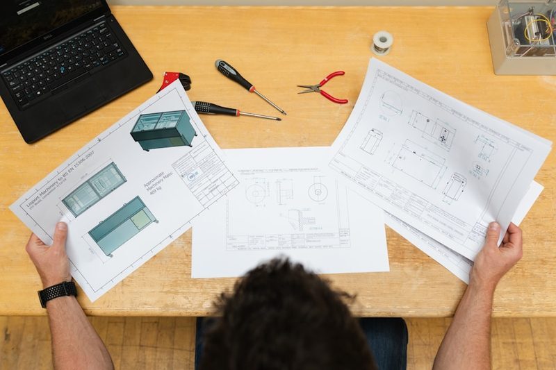
Thread quality is verified with go/no-go plug gauges: the GO side must thread in without excessive resistance to the specified depth, and the NO-GO side must not enter more than about two turns. Gauges control the pitch diameter, the functional dimension of the joint, per ISO 965 or ASME B1.1. Modern CNC shops routinely hold pitch-diameter tolerances of ±0.005 mm on fine metric threads and surface finish of Ra 0.8–1.6 µm on thread flanks, which matters for sealing in fluid fittings and fatigue resistance in aerospace brackets.
Worn taps cut undersized because their flute geometry has been partially relieved — they produce tighter threads than fresh taps on the same hole. ISO 9001:2015 certified suppliers replace taps on a proactive interval based on material and hole count rather than running them until they break, and document first-article inspection reports with full dimension and material certificates on request.
Common Thread Design Mistakes and How to Avoid Them
| Mistake | Consequence | Fix |
|---|
| Omitting the tolerance class (e.g., just "M6") | Loose or tight fits, assembly failures, quoting delays | Always specify 6H (metric) or 2B (Unified) |
| Specifying drill depth instead of thread depth | Broken taps, incomplete threads at the bottom of blind holes | Give both values; drill depth = thread depth + 1–1.5 × pitch |
| Over-deep threads "to be safe" | Higher cost, higher tap-breakage risk, no strength gain | Keep engagement at 1.0–1.5D unless analysis says otherwise |
| Threads too close to part edges | Thin walls, thread stripping during assembly | Leave adequate wall thickness around every tapped hole |
| Mixing metric and Unified threads in one assembly | Wrong mating parts, rework | Match the standard to the region and the mating component |
| Fine-pitch threads in galling-prone stainless without lubricant or coating | Galling, torn flanks, seized fasteners | Use coarse pitch, specify thread lubricant or surface treatment |
How SOMI Custom Parts Can Help
At SOMI Custom Parts, threading is a core capability rather than an afterthought. Our engineers review every drawing for manufacturability before quoting — checking thread depth, blind-hole clearance, tap drill sizes and tolerance classes so that threaded features machine correctly the first time. We machine standard metric and Unified threads across aluminum, stainless steel, titanium and engineering plastics, hold pitch-diameter tolerances to ±0.005 mm, and verify threads with go/no-go gauges and first-article inspection on a documented quality system. Send us your 3D model or 2D drawing through our inquiry page, or learn more about our company and capabilities on our About Us page — we respond with feasibility feedback, pricing and lead time, usually within one business day.
Frequently Asked Questions
What is the ideal thread engagement length for CNC machined parts?
For most applications, 1.0–1.5 times the nominal thread diameter is ideal. Aluminum structural joints use at least 1.5D because aluminum has lower shear strength, and high-load designs may reach 2.0D — but only where load analysis justifies it. Beyond roughly 1.5D, extra thread length adds cost and tap-breakage risk without meaningful strength gain.
What is the difference between thread depth and drill depth?
Thread depth is the functional length of usable thread; drill depth is the total depth of the hole before tapping. For blind holes the drill depth must be 1–1.5 pitches longer than the thread depth to leave room for the tap's chamfer and for chips. Specify both on the drawing.
Why should I specify 6H or 2B tolerance classes?
6H (metric) and 2B (Unified) are the standard industrial classes that give consistent, functional fits with standard tooling and gauging. Leaving the class off the drawing forces the machinist to guess, which causes loose or tight assemblies. Tighter classes like 5H or 3B add machining and inspection cost and should be used only when function requires.
When should I use thread milling instead of tapping?
Use thread milling for very small or very large threads, hardened materials above about 45 HRC, titanium and nickel alloys, or when a blind hole is deep and chip evacuation is a problem. Tapping remains the fastest, cheapest choice for standard sizes in aluminum, steel and brass.
Why do taps break in blind holes?
Most blind-hole tap breakage comes from chip packing at the bottom, an undersized tap drill (a hole 0.1–0.2 mm small raises tapping torque by 15–25%), or an interrupted feed in work-hardening materials. Spiral-flute taps, correct drill sizes and continuous rigid-tapping cycles prevent the majority of breakages.
Conclusion
Threads and tapped holes look simple in CAD but are among the highest-risk features in CNC machining. Following the design rules in this guide — standard sizes, explicit tolerance classes, engagement of 1.0–1.5D, correct blind-hole clearance, and the right threading method for the material — keeps parts manufacturable, affordable and reliable. When you need a partner who treats thread specification seriously, browse our CNC machined parts or send your design to SOMI Custom Parts for a feasibility review and quotation. You can also read more machining guides on our blog to sharpen your next design.