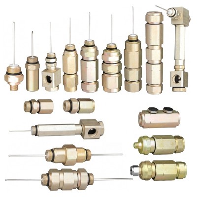
QR500 Coaxial Cable Performance: Wholesale CATV Connectors Explained
As we dive into the world of QR500 coaxial cable performance, we need to talk about something often overlooked but critically important: the connectors. They might seem small, but these unsung heroes play a massive role in how well your network performs.
I'll guide you through why the quality, installation, and environment surrounding your Wholesale CATV Connectors can make or break your data transfer rates, signal integrity, and overall system reliability.
The Silent Architects: Why Quality Wholesale CATV Connectors Are Essential
In any high-performance network, from sprawling CATV infrastructures to residential broadband setups, every component matters. But while we often focus on the cable itself, the connectors are the true gatekeepers of signal flow. They are the silent architects that-when chosen and installed correctly-ensure seamless connectivity. Conversely, a poor-quality connector can become the single point of failure that brings an entire system to its knees.
Making the Link: The Foundational Role of Connectors
At its core, a coaxial connector's job is to bridge the gap between cables and equipment, or between two cable segments, without interrupting the signal's path or its protective shielding. They are not just mechanical fasteners; they are critical components in the electrical path that must maintain the cable's characteristic impedance and shield against interference. A high-quality connector ensures that the signal passes from one point to another with minimal loss and reflection, preserving the integrity of the data or video being transmitted. This role is foundational because even the most advanced QR500 cable is only as good as the connector terminating it. A poorly designed or implemented connector can introduce significant signal degradation, effectively turning a high-spec cable into a bottleneck. The reliability of telecommunication systems, from base stations to broadband internet, is directly impacted by the quality and selection of these crucial components.
The Domino Effect: How Connectors Influence Speed and Reliability
The influence of a connector extends far beyond a simple physical link, creating a domino effect that impacts both speed and long-term reliability. A single, poorly installed or low-quality connector can set off a chain reaction of negative consequences.
- Signal Loss (Insertion Loss): Every time a signal passes through a connection, a tiny fraction of its energy is lost. High-quality connectors are engineered to minimize this loss, but inferior ones can cause significant attenuation, weakening the signal to the point where it becomes unusable. This leads to pixelation in video, dropped calls, and slower internet speeds.
- Signal Reflection (Return Loss): When the connector's impedance doesn't perfectly match the cable's, a portion of the signal is reflected back toward the source. These reflections can corrupt the original signal, causing data errors and further slowing down the network.
- Interference (EMI/RFI): The connector must maintain the coaxial cable's shielding effectiveness. Gaps or poor construction can create openings for external electromagnetic interference (EMI) and radio-frequency interference (RFI) to leak in, introducing noise and corrupting the signal. This is especially problematic in environments with many electronic devices.
- Physical Failure: Beyond electrical performance, the mechanical integrity of a connector is vital for reliability. Loose connections, often caused by vibration or improper tightening, can lead to intermittent signal or complete failure. Corrosion from moisture ingress is another common failure mode, especially in outdoor installations, which degrades contact points and obstructs signal flow.
Ultimately, these small issues compound, leading to a degraded user experience and increased maintenance costs. What might start as a "minor" glitch caused by a connector can quickly cascade into widespread network instability.
Choosing Wisely: A Look at Common Wholesale CATV Connectors
Selecting the right connector is crucial and depends heavily on the specific application, frequency range, power requirements, and environmental conditions. Here’s a look at three common types you'll encounter in CATV and related industries.
BNC Connectors: For Specific Impedance Needs
The Bayonet Neill-Concelman (BNC) connector is renowned for its quick connect/disconnect bayonet locking mechanism, making it ideal for test equipment, analog and digital video, and radio applications where frequent changes are necessary.
- Impedance Matching: BNC connectors are available in both 50-ohm and 75-ohm versions. This is their key feature; matching the connector's impedance to the cable's is critical for preventing signal reflection. While 50-ohm BNCs are standard for data and RF transmission, 75-ohm versions are used for video applications.
- Performance: They are generally reliable for frequencies below 4 GHz. Above this, the design can start to radiate signals, limiting its high-frequency stability.
- Applications: You'll find BNCs on everything from old 10base2 Ethernet networks to modern broadcast video equipment (SDI), nuclear instrumentation, and lab test gear like oscilloscopes.
F-Type Connectors: The CATV Workhorse
The F-Type connector is the undisputed standard for cable television (CATV), satellite television, and cable modems. Its design prioritizes cost-effectiveness and solid performance for 75-ohm systems.
- Design: It features a threaded coupling mechanism that provides a secure, vibration-resistant connection. A unique aspect is that the cable's own center conductor often serves as the male pin, which simplifies the design but demands proper cable preparation.
- Performance: Standard F-Type connectors offer a good 75 Ω impedance match for frequencies well over 1 GHz, with some high-frequency designs supporting up to 3 GHz or more. They are designed to meet ANSI/SCTE specifications, ensuring industry-wide compatibility.
- Variations: The most common installation methods are crimp, twist-on, and compression. Compression connectors are now considered the industry standard for their superior sealing and reliability, providing better protection against moisture and signal leakage.
N-Type Connectors: When High Power Meets High Frequency
Invented by Paul Neill of Bell Labs (the "N" in N-Type), this connector was one of the first capable of transmitting microwave-frequency signals. It is larger and more robust than BNC or F-Type connectors, designed for high performance in demanding applications.
- Durability and Weatherproofing: N-Type connectors feature a threaded coupling that creates a secure and vibration-resistant link. Many are designed to be weatherproof (IP67 rated), making them ideal for outdoor use in base stations, antennas, and other harsh environments.
- Performance: They offer excellent performance with an impedance of 50 ohms, and are rated for frequencies up to 11 GHz, with some precision versions reaching 18 GHz. This makes them suitable for high-power, high-frequency systems like radar, satellite communications, and wireless infrastructure.
- Power Handling: Their larger size and robust construction allow them to handle more power than their smaller counterparts, which is critical in transmitter applications. A 75-ohm version also exists but is less common and must not be mated with the 50-ohm version to avoid damage.
Here's a comparison table to summarize the key characteristics:
| Feature | BNC Connector | F-Type Connector | N-Type Connector |
|---|---|---|---|
| Primary Application | Video, Test Equipment | CATV, Satellite, Cable Modems | RF, Microwave, Base Stations |
| Impedance | 50Ω and 75Ω | 75Ω | 50Ω (most common), 75Ω |
| Coupling Mechanism | Bayonet Lock | Threaded | Threaded |
| Frequency Range | Up to 4 GHz | Up to 3 GHz (typical) | Up to 11-18 GHz |
| Key Advantage | Fast connect/disconnect | Cost-effective, secure | High power, robust, weatherproof |
Beyond the Surface: What Defines a High-Performance Wholesale CATV Connector?
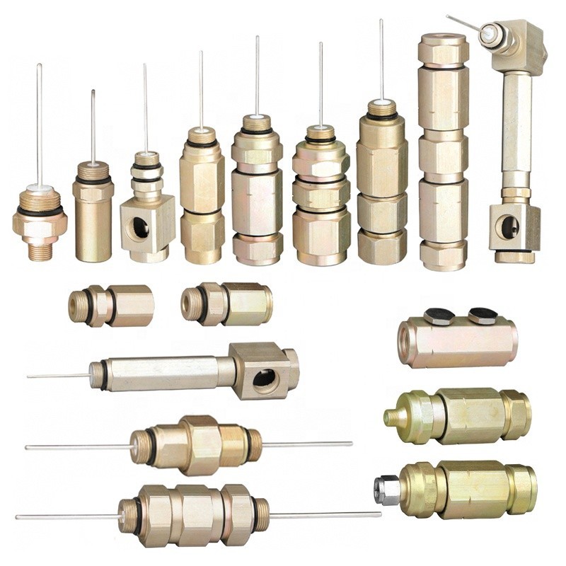
Not all connectors are created equal. While two connectors might look similar, their performance can vary dramatically based on the quality of their materials, the precision of their manufacturing, and the nature of their surface coatings. Understanding these subtle but critical details is the key to differentiating a truly high-performance connector from a standard one.
Craftsmanship and Materials: The Backbone of Signal Integrity
The foundation of a reliable connector lies in its core materials and the craftsmanship behind its production. These choices directly influence everything from durability to electrical performance.
- Body Materials: Most RF connector bodies are made from brass, which offers a good balance of machinability, strength, and cost. For more demanding applications, stainless steel is used for its superior strength and corrosion resistance. These materials are chosen for their electrical performance, mechanical durability, and reliability in high-frequency environments.
- Contact Materials: The center pin, or contact, is arguably the most critical component. It is typically made from beryllium copper because of its excellent spring properties, which ensure a reliable and repeatable connection over many mating cycles. This is often where a CNC Turning Parts Supplier showcases their value, as the precision of these small, intricate parts is paramount.
- Dielectric Insulators: The insulator separates the center conductor from the outer shell and is crucial for maintaining the connector's impedance. Polytetrafluoroethylene (PTFE), often known by the brand name Teflon, is the most common material due to its low signal loss and high-temperature resistance. In some high-precision air dielectric connectors, materials like Ultem 1000 may be used instead.
- Manufacturing Process: High-quality connectors are produced using precision CNC machining. This ensures that every part meets tight tolerances, which is essential for consistent electrical performance at high frequencies.
The choice of materials is a balancing act between performance, durability, and cost. While a basic brass connector might suffice for a simple indoor application, a military or aerospace system will demand stainless steel construction and high-grade dielectrics to ensure mission-critical reliability.
The Gold Standard: Why Plating Matters
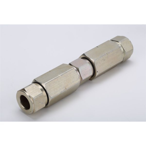
The thin layer of metal plated onto the connector's body and contacts plays an outsized role in its performance and longevity. The two most common plating materials are nickel and gold, each with distinct advantages.
Gold Plating:
- Superior Conductivity and Corrosion Resistance: Gold is an excellent electrical conductor and is highly resistant to oxidation and corrosion. This makes it the ideal choice for ensuring a clean, low-resistance connection, especially for low-voltage signals where even a small amount of corrosion can disrupt data flow. For outdoor connectors exposed to humidity or salt spray, gold plating is the safest choice for long-term integrity.
- Ideal for Signal Integrity: Because gold is a soft metal, it creates a large contact area when mated, further reducing contact resistance, which is critical for preserving signal integrity in high-fidelity or high-speed data applications.
Nickel Plating:
- Durability and Cost-Effectiveness: Nickel is significantly harder than gold, offering superior resistance to wear and scratching. This makes it a great choice for connectors that undergo frequent plugging and unplugging. It's also much more affordable than gold.
- Industrial Workhorse: Nickel provides good protection against environmental factors and has better thermal stability, making it suitable for high-power industrial applications.
The Best of Both Worlds: Often, the best connectors use both materials strategically. A layer of nickel is first applied to the base metal (like brass or copper) to act as a barrier. This nickel underplate prevents the copper from migrating through the final gold layer, a process that can cause corrosion. The gold is then plated on top to provide the superior contact surface. This multi-layered approach combines the durability of nickel with the conductivity and corrosion resistance of gold.
The Precision Factor: Understanding Connector Tolerances
In the world of high-frequency signals, precision is not a luxury—it's a necessity. The physical dimensions of a connector and its internal components have a direct and measurable impact on electrical performance. This is where manufacturing tolerances come into play.
Tolerances refer to the permissible limit of variation in a physical dimension. For RF connectors, these tolerances are measured in micrometers (or thousandths of an inch). Even tiny deviations can cause significant problems.
- Impedance Control: The characteristic impedance of a connector (e.g., 75 ohms) is determined by the physical dimensions and spacing between the center conductor and the outer shield. If manufacturing tolerances are loose, this spacing can vary, leading to impedance mismatches. Impedance mismatch is a primary cause of signal reflections (poor return loss), which degrades signal quality.
- Repeatable Performance: Tight tolerances ensure that every connector produced performs identically. This is critical for engineers designing complex systems who rely on components behaving exactly as specified in their datasheets. Inconsistent performance from one connector to the next can lead to endless troubleshooting.
- Mechanical Mating: Precision ensures that male and female connectors mate perfectly every time. Poor tolerances can lead to loose connections that are susceptible to vibration, or connections that are too tight and damage the components upon mating.
For high-frequency signals like those in CATV systems, even minuscule dimensional changes alter how the electromagnetic field travels through the connector. For instance, a premier manufacturer might hold a tolerance of just 0.003 inches, whereas a standard connector might allow for variations as large as 0.010 inches. This difference in precision is what separates a connector that works flawlessly at gigahertz frequencies from one that introduces unacceptable levels of signal loss and reflection.
Weathering the Storm: Environmental Impacts on Wholesale CATV Connectors
A network's reliability is often tested by the environment it inhabits. For CATV connectors, especially those installed outdoors, the daily and seasonal battle against temperature swings, moisture, and contaminants is a critical factor in their long-term performance. Even the most well-designed connector can fail if it’s not properly equipped to handle its surroundings.
Temperature's Toll: Expansion, Contraction, and Signal Degradation
Temperature fluctuations are a constant and insidious threat to the stability of a coaxial connection. The various materials that make up a connector and cable—metals like copper and brass, and dielectrics like PTFE—all expand and contract at different rates as temperatures rise and fall. This differential expansion can wreak havoc on a connection in several ways:
- Mechanical Stress and Loosening: As a connector cycles between hot and cold, the repeated expansion and contraction can cause threaded connections to loosen over time. This creates an intermittent or high-resistance connection, leading to signal loss and instability. In extreme cold, materials contract, which can physically stress and even cause micro-fractures in solders or crimps.
- Impedance Changes: The dielectric material inside a coaxial cable is particularly sensitive to temperature. Most microwave cable assemblies exhibit negative temperature coefficients of electrical length, meaning the signal's travel time changes with temperature. Notably, the common PTFE dielectric undergoes a material phase change around room temperature (19-25°C), causing a sudden change in its volume and dielectric constant. This abrupt shift alters the cable's characteristic impedance, leading to signal reflections and performance degradation that can be very difficult to diagnose.
- Condensation: When a connector cools rapidly, condensation can form inside it. This introduces moisture—the primary enemy of RF connections—directly at the most vulnerable point, setting the stage for corrosion and signal loss.
Fighting Off Moisture and Contaminants
Moisture is the single most common cause of coaxial connector and cable failure. Its presence, whether from rain, humidity, or condensation, initiates a cascade of destructive processes.
- Corrosion: When moisture gets inside a connector, it creates an electrolytic cell between the different metals, accelerating corrosion. Corrosion on the contact surfaces dramatically increases resistance, attenuates the signal, and can even create non-linearities that introduce intermodulation distortion. In CATV installations that also carry DC power, the corrosion process is sped up significantly.
- Changes in Dielectric Constant: Water trapped inside a connector or absorbed by the cable's dielectric material changes the effective dielectric constant of the transmission line. This alters the cable's impedance, causing a mismatch that leads to increased signal reflection (VSWR) and insertion loss. In high-frequency systems, this effect can be so severe as to appear like a dead short.
- Freezing: In cold climates, any trapped moisture can freeze and expand. This expansion can exert immense physical pressure on the internal components of the connector, forcing contacts apart, cracking the dielectric, and compromising the weatherproof seals, which ironically allows even more moisture to enter later.
Dust, salt spray (in coastal areas), and industrial pollutants are also significant threats. They can coat contact surfaces, preventing a clean electrical connection, and some chemicals can actively degrade the plating and plastic components of the connector.
Specialized Solutions for Harsh Conditions
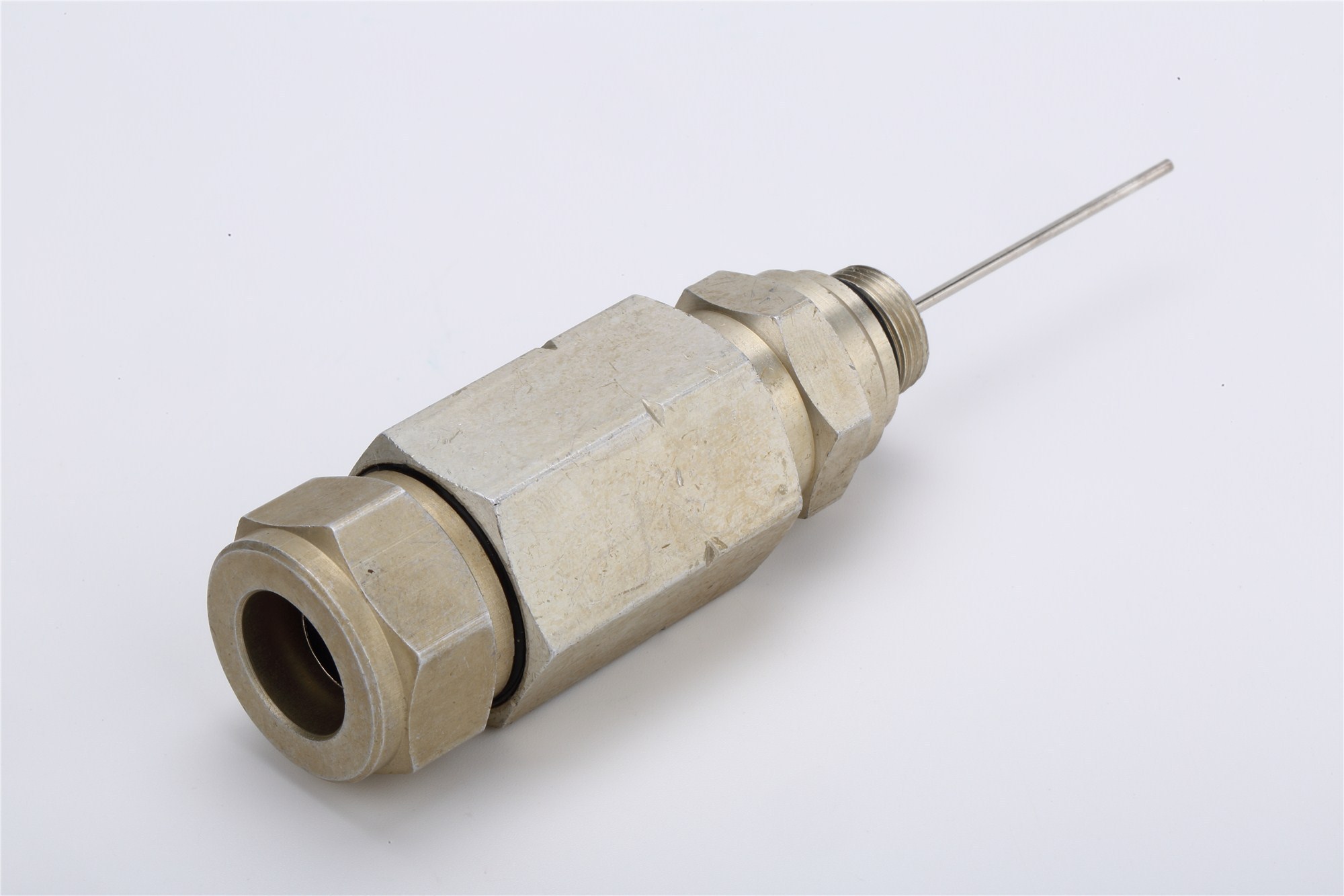
To combat these environmental challenges, manufacturers have developed a range of specialized connectors designed for harsh conditions. These solutions focus on robust sealing and durable materials.
- Waterproof (IP-Rated) Connectors: Connectors with an Ingress Protection (IP) rating, such as IP67 or IP68, are designed to be completely sealed against dust and water. They achieve this using O-rings and gaskets at every potential entry point—at the mating interface, the panel mount, and the cable entry point. An IP67-rated connector can be submerged in up to one meter of water for 30 minutes without leaking.
- Corrosion-Resistant Plating: For marine or industrial environments, standard plating may not be sufficient. Specialized platings like tin-nickel or the use of solid stainless steel bodies offer enhanced protection against corrosion and chemical exposure. These materials are often validated through extensive salt spray testing (e.g., 720 hours) to prove their resilience.
- Hermetically Sealed Connectors: For the most extreme applications, such as aerospace or military systems, hermetically sealed connectors provide a complete, gas-tight seal. These connectors use glass-to-metal seals to ensure no air or moisture can penetrate, offering the ultimate protection but at a significantly higher cost.
- External Weatherproofing Methods: In addition to using specialized connectors, external sealing methods provide an extra layer of protection.
- Self-amalgamating tape: This rubber-based tape fuses to itself when stretched and wrapped around a connection, creating a solid, waterproof barrier.
- Weatherproof enclosures: Placing splitters and connections inside a PVC or similar weatherproof box physically shields them from the elements.
- Heat-shrink tubing with sealant: Tubing lined with a heat-activated adhesive provides a tight, waterproof seal around the connector and cable jacket.
By selecting connectors and protection methods appropriate to the installation environment, network operators can safeguard their infrastructure against the elements, ensuring long-term reliability and minimizing costly service calls.
The Human Touch: Installation and Testing Best Practices for Wholesale CATV Connectors
Even the highest-quality connector will fail if not installed and tested correctly. The "human touch"—the skill, precision, and diligence of the technician—is the final and most crucial element in ensuring a robust and reliable network. Adhering to best practices for termination, cable management, and performance testing separates a professional-grade installation from one that is plagued with problems.
Perfecting the Connection: The Art of Proper Termination
Termination is the process of attaching a connector to the end of a coaxial cable. It is both an art and a science, requiring the right tools, the correct technique, and attention to detail. A single mistake here can introduce significant signal loss and reflection.
1. Use the Right Tools for the Job:
- Cable Stripper: A high-quality, dual-blade coaxial stripper is essential. It is designed to cut the jacket, shield, and dielectric to the precise, specified lengths in one action. Using a knife or incorrect tool can nick the center conductor or leave the strip lengths inaccurate, compromising the connection.
- Compression Tool: For F-type connectors, a compression tool is the industry standard. It applies uniform pressure to create a weather-resistant, 360-degree seal. Avoid twist-on connectors for permanent installations, as they are less reliable and offer a weaker signal. Crimp connectors can be effective but require a precise crimp tool and die; a poor crimp can be just as bad as a loose twist-on.
2. Follow the "Prep, Prep, Prep" Mantra:
- Clean, Square Cut: Start by making a clean, perpendicular cut on the end of the cable with a dedicated cable cutter. A crooked cut can prevent the connector from seating properly.
- Accurate Strip: Follow the connector manufacturer's specifications for strip lengths (typically a "1/4-inch, 1/4-inch" prep for RG6). The inner foam dielectric should be flush with the base of the connector body when inserted.
- Fold Back the Shield: Carefully fold the braided shield back over the cable jacket, ensuring no stray strands make contact with the center conductor—a common cause of shorts.
- Seat and Compress: Push the connector firmly onto the prepped cable until the dielectric is seated. Then, use the compression tool to secure the connector. A properly compressed fitting will show a uniform seal with no gaps.
A common mistake is leaving the center conductor too long or too short. It should protrude just slightly past the end of the connector, about 1/8 to 3/16 of an inch, to ensure a solid connection within the female port.
Organized Cables, Optimal Performance
In data centers, headends, or even residential media closets, how cables are organized is directly linked to network performance and maintainability. A tangled mess of wires, often called "cable spaghetti," is more than just an eyesore.
- Improves Airflow and Cooling: Tightly bundled and disorganized cables can block airflow around equipment, causing components to overheat. This can lead to thermal shutdowns, reduced performance, and a shorter equipment lifespan. Proper management ensures cooling systems can function efficiently.
- Reduces Signal Interference: Running data cables parallel to power cables can introduce electromagnetic interference (EMI), which corrupts signals and causes data errors. Best practice dictates separating power and data cables, routing them on opposite sides of a rack or in separate trays.
- Simplifies Maintenance and Troubleshooting: When every cable is neatly routed and clearly labeled, technicians can identify, trace, and replace faulty connections in minutes instead of hours. This dramatically reduces Mean Time To Repair (MTTR) and minimizes costly downtime.
- Protects Cable Integrity: Organized routing using cable managers, trays, and Velcro straps prevents cables from being kinked, stretched, or pinched. This protects against physical damage that causes signal degradation and eventual failure.
Measuring Success: Crucial Performance Tests
After installation, performance testing is the only way to verify that the connectors and cables are performing to specification. The two most fundamental tests for any coaxial network are Insertion Loss and Return Loss. These are typically performed with a Vector Network Analyzer (VNA) or a specialized Cable and Antenna Analyzer.
Insertion Loss: How Much Signal Do We Lose?
Insertion loss, also known as attenuation, measures the amount of signal energy lost as it travels through a cable and its connectors. It is expressed in decibels (dB). All cables and connectors will have some insertion loss, but the goal is to keep it to an absolute minimum.
- What it Indicates: High insertion loss means the signal is weakening significantly, which can be caused by excessive cable length, poor quality materials, or faulty connector terminations.
- Why it Matters: In a CATV system, high insertion loss leads to a weak signal at the television, resulting in a snowy picture, pixelation, or a complete loss of certain channels. In a broadband system, it results in slow internet speeds and connection dropouts. Insertion loss testing is crucial for pinpointing degraded components before they cause a total system failure.
Return Loss: Bouncing Back to Quality
Return loss measures the amount of signal that is reflected back toward the source due to impedance mismatches within the cable or, more commonly, at the connector points. It is also measured in dB, but unlike insertion loss, a higher return loss value is better, as it indicates that less signal is being reflected.
- What it Indicates: A poor (low) return loss value is a clear sign of an impedance mismatch. This is often caused by a poorly installed connector, a kinked cable, or a faulty component like a splitter.
- Why it Matters: Reflected signals act as noise, interfering with the original signal and causing data corruption and distortion. In digital TV, this can manifest as "ghosting" or tiling on the screen. In data systems, it forces retransmissions, crippling throughput. A return loss of 15 dB or better is a common target for a healthy cable and antenna system.
Together, these tests provide a comprehensive picture of the health of the physical layer of your network, ensuring every connection is a strong link rather than a weak point.
Making the Smart Choice: Strategizing Your Wholesale CATV Connector Selection
Choosing the right wholesale CATV connector is more than just a technical decision; it's a strategic one that impacts network performance, long-term operational costs, and overall reliability. A thoughtful selection process involves aligning the component's capabilities with network demands, looking beyond the initial price to understand its true value, and cultivating strong relationships with suppliers.
Aligning Connectors with Network Needs
The first step in any procurement process is to clearly define the requirements of the network. A connector that is perfect for a residential indoor setup is likely inappropriate for a high-power broadcast tower. Key considerations include:
- Frequency Range: Ensure the connector is rated for the frequencies your network operates on. Using a connector outside its specified frequency range will lead to significant signal loss and reflection. For example, while standard F-type connectors work well for CATV frequencies, higher-frequency microwave systems require precision connectors like N-type or SMA.
- Impedance Matching: The connector's impedance (typically 75 ohms for CATV) must match the cable's impedance. An impedance mismatch is a primary cause of poor return loss and signal degradation.
- Environmental Conditions: Will the connector be used indoors in a climate-controlled room, or outdoors exposed to rain, sun, and temperature extremes? Outdoor applications demand connectors with robust weather sealing (e.g., IP67 rating) and corrosion-resistant materials.
- Power Handling: For applications involving transmitters, such as in the headend, the connector must be able to handle the required power levels without overheating or arcing.
- Mechanical Durability: Consider how often the connection will be made and unmade. Connectors in a test lab, for example, require high mating cycles, whereas a connection to a permanent antenna does not.
By carefully matching the connector's specifications to the network’s specific needs, you lay the groundwork for a reliable and efficient system.
Beyond the Price Tag: Long-Term Value and Maintenance
While the initial purchase price of a connector is an important factor, it represents only a fraction of its Total Cost of Ownership (TCO). A cheaper connector can often become far more expensive in the long run.
- Total Cost of Ownership (TCO): TCO includes the initial purchase price plus all direct and indirect costs over the component's lifecycle. This encompasses operating costs, maintenance expenses (including labor for troubleshooting and replacement), and the cost of downtime caused by failures.
- The Cost of Failure: A low-quality connector that fails can cause significant network downtime. The cost of sending a technician to diagnose and replace a single failed connector—especially in a remote or hard-to-reach location—can easily exceed the initial savings of buying a cheaper part by hundreds of times. A factory that deployed cheaper connectors for its sensor network, for example, faced frequent failures due to vibration, leading to costly downtime; switching to more robust N-type connectors reduced maintenance costs by 40%.
- Durability and Reliability: High-quality connectors are made from better materials with tighter tolerances, leading to a much lower failure rate. They are less susceptible to environmental factors and maintain a stable connection over many years. This enhanced reliability translates directly to lower maintenance costs and higher customer satisfaction. For example, while generic connectors might last a few years, a name-brand, properly installed connector can last for decades.
Investing in a higher-quality connector from a reputable manufacturer is an investment in long-term network stability and a lower TCO. The peace of mind and reduced operational expenses far outweigh the minimal upfront savings of a budget component.
Building Strong Supplier relationships
In the wholesale electronics market, your suppliers are more than just vendors; they are your partners. Cultivating strong, transparent relationships is essential for ensuring a stable and reliable supply chain.
- Communication and Transparency: Establish open and consistent lines of communication with your suppliers. A good partner will be transparent about their production capacity, lead times, and any potential supply chain issues. This honesty builds trust and allows for better strategic planning.
- Technical Support and Expertise: A reliable supplier offers more than just parts; they provide technical expertise. They should have engineering and quality assurance personnel who can help you select the right component for your application, provide detailed specifications, and assist with any troubleshooting. This is especially true when working with authorized distributors who have direct access to the connector manufacturer.
- Quality and Consistency: A strong supplier relationship ensures you receive consistent, high-quality products. They will have robust quality control processes and will notify you of any product design changes or discontinuations that could affect your operations.
- Mutual Growth: Treat your suppliers as an extension of your own team. When you align your goals, negotiate fair terms, and provide constructive feedback, you create a partnership where both parties are invested in each other's success. Such a relationship can lead to better pricing, priority support, and even collaboration on innovative solutions.
Choosing the right supplier is as critical as choosing the right connector. A partnership built on trust, communication, and a shared commitment to quality is one of the most valuable assets a network operator can have.
I hope this deep dive has shown you that selecting and maintaining high-quality Wholesale CATV Connectors isn't just a technical detail; it's a fundamental aspect of building a reliable and high-performing network. These small but mighty components are the gatekeepers of your signal, and their quality directly impacts everything from picture clarity on a television screen to the speed and stability of a broadband internet connection.
By paying close attention to material quality, manufacturing precision, environmental factors, and installation practices, you can ensure your QR500 coaxial cable system delivers consistent and excellent performance for years to come. Looking beyond the initial price tag to consider the total cost of ownership and building strong partnerships with your suppliers are strategic moves that pay long-term dividends in reduced maintenance and superior reliability. The next time you look at a coaxial connection, I hope you see not just a piece of hardware, but a critical link demanding care and precision.
What are your experiences with connector failures or successes? Share your thoughts in the comments below and let's continue the conversation