How to Read Engineering Drawings: A Buyer's Guide to Tolerances, GD&T, and Notes
Engineering drawings are the contract between you and your CNC machining supplier. A single misread tolerance, a wrong datum, or an ignored note can turn an entire batch of parts into expensive scrap. Yet many buyers approve drawings and quotes without fully understanding what they are approving. This buyer's guide teaches you how to read engineering drawings — title blocks, dimensions, tolerances, GD&T, and notes — so you can quote parts accurately, catch costly errors early, and communicate clearly with your CNC machining parts partner.
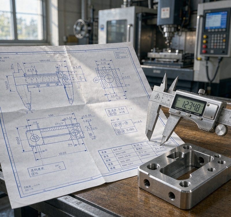
A properly annotated engineering drawing defines geometry, tolerances, material, and quality in a language every machinist and inspector can read.
What Are Engineering Drawings?
An engineering drawing is the authoritative technical description of a part: its geometry, size, material, surface finish, and acceptance criteria. It follows international conventions defined by ASME Y14.5 (the American GD&T standard, latest edition 2018) and ISO GPS standards such as ISO 1101 and ISO 2768. Every line weight, symbol, and note placement has a precise meaning.
As one experienced design engineer puts it: drawings are a language, not a picture. When you treat a drawing like a picture to be visually scanned rather than a language to be read systematically, you miss the grammar — and the grammar is where the cost and quality live. Interestingly, the drawings that cause the most expensive errors are rarely the complex ones. They are the straightforward drawings where a reader assumed they already understood the context and skipped a step.
The 8-Step Reading Sequence
Professional engineers and inspectors follow a fixed workflow every time, even on drawings that look simple. Adopt the same discipline and you will catch the ambiguities that cause rework:
Revision, units, standard, material
First-angle vs third-angle
“Unless Otherwise Specified” note
Orthographic, section, detail
Explicit callouts vs defaults
Symbols, values, datums
General and flag notes
Resolve ambiguity before cutting
Read the title block first, the notes last — but when quoting, price the notes first.
Start With the Title Block
The title block in the bottom-right corner is the part’s passport. Before you read a single dimension, confirm:
- Part number and name — is this the right drawing?
- Revision letter — always check it matches the file you sent to manufacturing. Old revisions are one of the most common sources of wrong parts.
- Units — millimeters or inches. Mixing units is a classic scrapping error: 0.1 mm is not the same as 0.1 inch.
- Material specification — e.g. AL6061-T6, SUS304, 4140 — plus any hardness or heat-treatment requirement.
- Governing standard and general tolerance — e.g. ISO 2768-mK, which sets the default tolerance for all untoleranced dimensions.
- Scale and surface finish — never measure dimensions directly off a printed drawing; scale is informational.
Views and Projections: Building the 3D Picture
Most drawings show the part from several directions using orthographic projection: front, top, and side views, aligned so the reader can mentally reconstruct the 3D shape. Hidden features appear as dashed lines; a section view (marked A–A) cuts through the part to reveal internal geometry; detail views zoom in on small critical areas such as O-ring grooves; auxiliary views show inclined surfaces at true size.
Before trusting any view, verify the projection method — the single most common source of mirrored, unassemblable parts:
| Projection | Where used | View layout | Risk if misread |
|---|---|---|---|
| Third-angle | USA, Canada, Japan | Top view sits above the front view | Mirrored or flipped parts that fail assembly |
| First-angle | Europe, most of Asia | Top view sits below the front view |
A small standardized projection symbol near the title block identifies which system applies. Checking it takes 30 seconds and eliminates one of the most expensive error families in manufacturing.
How to Read Dimensions and Tolerances
Dimensions define size; tolerances define acceptable variation. Every dimension must have a tolerance — either stated directly or inherited from the general tolerance note. Five common formats appear on real drawings:
The same 20.00 mm dimension can carry very different meanings depending on how it is annotated.
The tolerance hierarchy is simple: an explicit callout on a feature overrides the general tolerance block; a boxed basic dimension has no tolerance of its own — its tolerance comes from the GD&T frame it feeds; and a parenthesized reference dimension is never inspected. The most common general tolerance standard is ISO 2768, which applies default values by nominal dimension range:
| Nominal range (mm) | Fine (f) | Medium (m) | Coarse (c) |
|---|---|---|---|
| 0.5 to 3 | ±0.05 | ±0.1 | ±0.2 |
| 3 to 30 | ±0.1 | ±0.2 | ±0.5 |
| 30 to 120 | ±0.15 | ±0.3 | ±0.8 |
| 120 to 400 | ±0.2 | ±0.5 | ±1.2 |
| 400 to 1000 | ±0.3 | ±0.8 | ±2.0 |
ISO 2768-1 linear tolerances by class; the common drawing callout is ISO 2768-mK (medium dimensions + standard geometry).
What can a CNC shop actually hold? Capability depends on process, material, geometry, and setup — but these typical values help you judge whether a callout is realistic:
| Process | Standard tolerance | Precision tolerance |
|---|---|---|
| 3-axis CNC milling | ±0.05 mm | ±0.01 mm |
| 5-axis CNC milling | ±0.05 mm | ±0.01 mm |
| CNC turning | ±0.05 mm | ±0.005 mm |
| CNC grinding | ±0.005 mm | ±0.001 mm |
| Reaming (holes) | H7 fit | H6 fit |
| Wire EDM | ±0.01 mm | ±0.002 mm |
One more subtlety: temperature. Aluminum expands about 23 µm per meter per °C — a 100 mm aluminum part grows 2.3 µm for every degree of temperature change. Once you specify tolerances tighter than about ±0.01 mm, inspection temperature must be part of the specification, not an afterthought.
GD&T Fundamentals: The Feature Control Frame
Geometric Dimensioning and Tolerancing (GD&T) extends ordinary ± dimensioning to control shape, orientation, location, and runout — properties a simple size tolerance cannot capture. ASME Y14.5-2018 defines 14 geometric characteristic symbols grouped into five categories:
| Category | Controls | Symbols | Datum needed? |
|---|---|---|---|
| Form | Shape of a single feature | Straightness, flatness, circularity, cylindricity | No |
| Profile | Shape of a line or surface | Profile of a line, profile of a surface | Usually |
| Orientation | Angle relative to a datum | Angularity, perpendicularity, parallelism | Yes |
| Location | Position relative to datums | Position (true position), concentricity, symmetry | Yes |
| Runout | Variation during rotation | Circular runout, total runout | Yes (axis) |
Note: ASME Y14.5-2018 steers users away from concentricity and symmetry toward position and profile, which control the same functions more reliably. You will still see the legacy symbols on older drawings.
The heart of GD&T is the feature control frame — a rectangular box read strictly left to right:
Symbol → tolerance value and modifier → datum references. Order matters: A, B, C is not the same as C, B, A.
Datums are the origin of all measurement. The machinist sets up the part on the primary datum first — that is why datum selection directly determines fixturing and inspection. A drawing without explicit datums leaves inspection open to interpretation, which is how disputes about “in or out of tolerance” start.
True Position vs Plus/Minus: The 57% Advantage
Here is the single most valuable GD&T insight for buyers. Conventional plus/minus dimensioning on a hole pattern creates a square tolerance zone: the hole center may drift ±X and ±Y. A GD&T true position callout creates a cylindrical zone around the true center. For the same worst-case corner reach, the cylindrical zone contains roughly 57% more usable tolerance area than the inscribed square:
Same assembly function, fewer rejected parts — this is the concrete economic argument for GD&T on hole patterns and bolt circles.
In practice this means a drawing with true position callouts is easier and cheaper to manufacture than one with tight ± coordinates, while guaranteeing the same functional fit. If your supplier pushes back on your ±0.02 mm hole coordinates, a position callout at ø0.1 with MMC may be the lower-cost solution that still assembles perfectly. When a position tolerance is specified at MMC, bonus tolerance grows as the hole departs from its minimum size — a cost-saving feature invisible to anyone unfamiliar with the convention.
General Notes and Flag Notes: The Hidden Cost Drivers
Notes carry manufacturing instructions that cannot be expressed through dimensions or GD&T alone. General notes sit in a block (usually upper or lower left of the sheet) and apply to the whole part; flag notes are numbered callouts tied to specific features. Both are mandatory unless explicitly marked as reference.
- “BREAK ALL SHARP EDGES 0.3 mm MAX” — deburring and edge treatment, often required for safety and handling
- “ANODIZE PER MIL-A-8625 TYPE II” — a coating specification that changes both appearance and corrosion behavior
- Heat treatment and hardness — e.g. “HARDNESS 28–32 HRC” — a process step that can dominate cost and lead time
- “INSPECT 100%” — full inspection callouts add metrology time and price
- Surface finish symbols — Ra 1.6–3.2 µm is standard machined; Ra 0.8 µm is a precision finish for bearing or sealing faces; Ra 0.1–0.4 µm needs grinding or polishing
- Thread callouts — M10×1.5 with 6H/6g tolerance (metric), 1/4-20 UNC 2B/2A (unified inch)
Ignoring notes is a leading cause of nonconforming parts, especially for processes like deburring, heat treatment, anodizing, and torque requirements. When quoting a job, read the notes last but price them first — they are often the majority of the part cost.
How SOMI Custom Parts Can Help
At SOMI Custom Parts, our engineering team reads every drawing systematically before quoting — title block first, notes last — and we flag ambiguity before it becomes scrap. As an ISO 9001:2015 certified precision manufacturer, we apply the same discipline to inspection: coordinate measuring machine (CMM) verification, first-article inspection, and material certificates where required.
If your drawing is incomplete — missing a datum, an unclear note, or an ambiguous tolerance — send it to us anyway. Our engineers will tell you what is missing and how to fix it, usually within the same day. Browse our full range of custom parts manufacturing services or read more buyer’s guides on our blog.
Frequently Asked Questions
What is the most important part of an engineering drawing?
The title block. It confirms the part number, revision level, units, material, scale, and governing tolerance standard before you interpret any dimension. Reading it first prevents the two most common failures: manufacturing from an obsolete revision and mixing millimeters with inches.
What does ±0.05 mm actually mean for a machined part?
It defines the acceptable range: a 20.00 mm dimension may measure anywhere from 19.95 to 20.05 mm. ±0.05 mm is a practical precision level for standard CNC milling and turning (many shops hold it routinely). Specifying ±0.01 mm or tighter raises cost exponentially and may require grinding or EDM plus CMM inspection — only apply it where the function demands it.
Do I need GD&T on my drawings?
For simple, non-critical features, a general tolerance note like ISO 2768-mK is enough. For mating surfaces, hole patterns, bores, and anything assembly-critical, GD&T is strongly recommended: a true position callout creates a cylindrical zone with ~57% more usable area than ± coordinates, which lowers manufacturing cost and rejects while guaranteeing the same fit. GD&T also removes ambiguity about how the part is measured.
What is the difference between first-angle and third-angle projection?
Third-angle projection (USA, Canada, Japan) places the top view above the front view; first-angle projection (Europe, most of Asia) places it below. A standardized symbol near the title block tells you which applies. Misreading the projection is a classic cause of mirrored parts that look fine visually but fail assembly.
Can SOMI help if my drawing is unclear or incomplete?
Yes — that is exactly what our engineering team does. We review every drawing before quoting, flag ambiguities such as missing datums or contradictory notes, and suggest DFM improvements that reduce cost without compromising function. You can send your drawings for a free review or reach us directly through our contact page.
Conclusion
Reading engineering drawings is a learnable skill — and for buyers, it pays back on every quote, every inspection, and every batch of parts. Start with the title block, verify the projection, understand the tolerance hierarchy, read GD&T frames left to right, and never skip the notes. Above all, when something is ambiguous, ask.
Working with a supplier who reads drawings the same way you do is half the battle. At SOMI Custom Parts, our engineers review your drawings before we quote, hold tolerances down to ±0.005 mm with CMM-backed inspection, and finish parts in-house for faster, more reliable lead times. Send us your engineering drawings for a free DFM review and quotation — or learn more about our company and quality system first. Your next part starts with a drawing that everyone reads the same way.