Designing Press-Fit and Slip-Fit Features for Precision CNC Parts
Press-Fit and Slip-Fit Features: The Micron-Level Design Decisions Behind Reliable CNC Assemblies
Every shaft-and-hole assembly comes down to one question: should the two parts stay locked together, or should they move? Press fits and slip fits are the two most common engineering fits in CNC machining, and the difference between them can be just a few microns of tolerance. Get that tolerance band right, and your assembly transmits torque, aligns precisely, and survives years of thermal cycling. Get it wrong, and you face cracked housings, seized shafts, or parts that rattle loose in service.
This guide walks through the engineering behind press-fit and slip-fit features for precision CNC machined parts: ISO 286 tolerance classes, interference values by material, machining methods that hold micron-level geometry, surface finish requirements, and the failure modes that separate a fit that works on paper from one that works on the shop floor.
Key takeaway: The most reliable fit is not the tightest one. It is the loosest fit that still delivers the required positional accuracy, load capacity, or motion behavior — held consistently across the entire production run with a process capability (Cpk) above 1.33.
What Are Press-Fit and Slip-Fit Features?
A press fit (also called an interference fit) is created when the shaft diameter is slightly larger than the hole diameter. During assembly, the shaft compresses slightly and the bore expands, generating contact pressure across the mating surfaces. The resulting friction locks the parts together without fasteners, adhesives, or keyways — ideal for bearings in housings, gears on shafts, bushings, dowel pins, and locating features. Roughly 35% of CNC machined assembly programs include at least one press-fit interface, making interference fit design one of the most common tolerance challenges in precision manufacturing.
A slip fit (or clearance fit) works the opposite way: the shaft is slightly smaller than the hole, leaving a controlled clearance so parts slide together easily by hand or light force. Slip fits allow assembly, disassembly, rotation, and thermal expansion without binding. They are the natural choice for guide shafts, locating pins, removable tooling, bearing housings, and any serviceable assembly.
Both fit types are standardized under ISO 286 (and ASME B4.1 in the U.S. system). The hole is typically specified as H7, always on the plus side of nominal; the shaft letter determines the resulting fit type.
Press Fit (Interference)
Shaft larger than hole; assembly requires force, hydraulic press, or thermal assistance. No relative movement intended.
- Transmits torque and axial loads without fasteners
- Permanent or semi-permanent joints
- Bearings, gears, bushings, dowel pins
Slip Fit (Clearance)
Shaft smaller than hole; parts slide together easily. Free sliding or rotation with controlled play.
- Easy assembly and disassembly
- Accommodates thermal expansion
- Guide shafts, locating pins, removable tooling
Key Benefits of Getting Fits Right in CNC Machining
Well-designed fits deliver measurable advantages across the product lifecycle — from the first prototype to years of field service.
Faster, Repeatable Assembly
Correct clearance means parts mate consistently without selective fitting, rework, or hammering — cutting assembly time and reducing scrap on the line.
Higher Joint Reliability
Proper interference prevents slipping under load and fretting wear, while correct clearance prevents binding and galling over the operating temperature range.
Lower Total Cost
Avoiding over-toleranced fits keeps machining time and inspection costs in check. Tightening a tolerance from ±0.02 mm to ±0.005 mm can double machining time and push scrap rates from under 2% to 5–15%.
Simpler Supply Chain
Standard ISO 286 classes (H7/g6, H7/p6) are universally understood, so drawings transfer cleanly between design teams and machining suppliers.
ISO 286 Tolerance Classes: The Language of Fits
ISO 286 defines tolerance zones with letter-number codes: uppercase letters (e.g., H) for holes, lowercase letters (e.g., g, p) for shafts. The hole-basis system — the most common in production — keeps the hole tolerance fixed at H7 and varies the shaft tolerance to control the fit. For a 25 mm nominal diameter, the practical classes are:
| Fit Type | ISO Class | Hole (mm) | Shaft (mm) | Result (mm) | Typical Use |
|---|---|---|---|---|---|
| Sliding slip | H7/g6 | 25.000–25.021 | 24.980–24.993 | 0.007–0.041 clearance | General sliding shafts, rotating parts |
| Tight slip | H7/h6 | 25.000–25.021 | 24.987–25.000 | 0–0.034 clearance | Location, alignment, minimal play |
| Light press | H7/p6 | 25.000–25.021 | 25.022–25.035 | 0.001–0.035 interference | Gears, pulleys, removable with press |
| Medium press | H7/s6 | 25.000–25.021 | 25.035–25.048 | 0.014–0.048 interference | Permanent drive fits, shrink fits |
A 0.014 mm interference on a 25 mm shaft is roughly one-fifth the thickness of a human hair — yet it generates enough holding force to transmit substantial torque without a keyway. But these tolerance bands assume perfectly round, cylindrical parts at 20 °C. On the shop floor you are dealing with real geometry: ovality, taper, surface roughness, and real temperatures. The drawing is the starting point, not the whole story.
Choosing Interference Values by Material
The fit you specify assumes both parts share similar mechanical behavior. In practice, material pairing drives the safe interference window. Aluminum has roughly one-third the elastic modulus of steel, so it deforms and yields far more easily — a 50 µm interference that works perfectly in steel can crack an aluminum housing. As a rule of thumb, reduce interference by 30–50% when the weaker member is aluminum, and add engagement length instead of interference to gain holding force.
| Material Pair | Recommended Interference | Key Concern |
|---|---|---|
| Steel → steel | 20–50 µm | High strength, low deformation |
| Steel → aluminum | 10–30 µm | Aluminum yields and cracks easily |
| Aluminum → aluminum | 5–20 µm | Low stiffness, loosening risk |
| Steel → plastic (POM, nylon) | 2–10 µm | Creep and relaxation over time |
Thermal expansion is equally important. Steel expands at roughly 11–13 × 10⁻⁶ /°C; aluminum at 22–24 × 10⁻⁶ /°C. A steel shaft in an aluminum housing that holds firmly at room temperature may loosen at 80 °C as the bore grows faster than the shaft. Always verify the worst-case interference or clearance across the full operating temperature range — never design for 20 °C alone.
Stainless-to-stainless warning: galling is the real risk here. Under pressure during press-fit assembly, stainless on stainless can cold-weld and seize. Use dissimilar hardness, assembly lubricant, or a surface treatment on one mating part.
Machining Methods That Hold Fit Tolerances
The achievable tolerance depends on the process you choose. Matching the process to the fit class — not the other way around — is what keeps cost under control.
| Process | Achievable Tolerance | Best For |
|---|---|---|
| Standard CNC | ±0.010–0.020 mm | Light press and general slip fits |
| Precision CNC | ±0.005–0.010 mm | Light-to-medium interference fits |
| CNC + reaming | ±0.003–0.008 mm | Bores: improved roundness and surface |
| CNC + grinding | ±0.001–0.005 mm | Hardened shafts, micron-level geometry |
For holes, reaming is faster and more repeatable in production, while boring gives finer diameter control and flexibility for custom tolerances and larger bores. For very tight shaft tolerances, grinding after heat treatment improves roundness, surface finish, and dimensional stability beyond what turning alone can hold — common for bearing shafts, hydraulic components, and precision rotating assemblies. The most cost-effective press-fit allocation: shaft ±0.005 mm (ground), hole ±0.010 mm (reamed) — tight control on the critical feature, standard CNC capability everywhere else.
Repeatability is the real challenge. Hitting a tolerance once is different from holding it across a run. Tool wear can drift a 10.000 mm bore to 10.008 mm after 50 parts without offset correction; machine and part thermal growth can shift dimensions 5–10 µm during extended cutting. Process capability (Cpk) matters more than nominal tolerance: a ±0.010 mm process with Cpk > 1.33 produces more reliable press fits than a nominal ±0.005 mm process with Cpk below 1.0.
Slip-Fit Clearance, Surface Finish, and Coatings
For slip fits, surface finish is as important as the dimensional tolerance. A rough surface consumes the effective clearance and accelerates wear on sliding surfaces. Precision sliding fits typically call for Ra 0.8–1.6 µm; keep critical mating surfaces at Ra 0.8 µm or better, and avoid Ra above 3.2 µm on tight-clearance features. Practical clearance guidance for CNC slip fits: 0.005–0.050 mm for most designs, with precision locating features capped near 0.030 mm maximum clearance and general sliding parts allowed 0.050–0.100 mm or more.
Surface treatments change diameters — often more than designers expect. Coating buildup must be included in the tolerance stack, or a fit that works in raw machining becomes too tight after finishing:
| Surface Treatment | Typical Build-Up | Effect on Slip Fit | Compensation |
|---|---|---|---|
| Type II anodizing | 0.005–0.025 mm total | Reduces clearance on shafts and bores | Machine undersize before anodizing |
| Hardcoat anodizing (Type III) | 0.025–0.075 mm total | Can turn a slip fit into an interference fit | Add pre-coating clearance allowance |
| Nickel plating | 0.010–0.050 mm per side | Can substantially tighten precision fits | Precision masking or post-machining |
| Chrome plating | 0.005–0.025 mm per side | Reduces clearance, raises hardness | Finish grind after plating |
Common Failure Modes and How to Prevent Them
Most fit failures trace back to three causes: too much interference for the material (cracking), tolerance stack-up that drives interference toward zero (loosening), and poor assembly alignment (deformation). Each is preventable with the right design and process choices.
Cracking
Most common in aluminum and thin-walled parts. A 50 µm interference that works in steel can crack an aluminum housing.
Fix: size interference for the weaker member, add wall thickness or engagement length, and use thermal assembly for sensitive materials.
Loosening
Often caused by tolerance stack-up leaving near-zero worst-case interference, later worsened by plastic creep or thermal mismatch.
Fix: verify minimum interference stays positive in the worst case; add knurling or retaining compound when creep is a risk.
Galling
Metal-to-metal sliding during press assembly produces surface tearing and seizure — especially stainless on stainless.
Fix: use assembly lubricant, dissimilar hardness, or a coating on one member.
Deformation & Misalignment
Uneven press force or misalignment distorts the bore and bends the shaft, causing vibration and premature wear.
Fix: guided fixtures, uniform force application, alignment verification — never hammering or impact pressing.
Chamfers make both fit types more robust: add a 0.5–1 mm × 30–45° lead-in chamfer on both male and female parts to guide insertion and protect edges. For assembly, mechanical pressing suits light-to-medium interference in strong materials; thermal assembly (heating the bore to roughly 100 °C, or chilling the shaft) is safer for fragile materials, thin walls, and heavy interference.
How SOMI Custom Parts Can Help
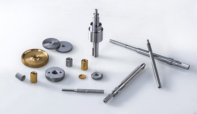
SOMI Custom Parts is a precision parts manufacturer specializing in CNC machining parts with tight-tolerance fit features. Our engineering team reviews every drawing for hole-and-shaft tolerance feasibility, coating buildup, wall stiffness, and realistic machining limits before release — because a fit that works in theory is worthless if it does not assemble on the shop floor.
We hold H7-class bores through precision CNC and reaming, h6-class shafts through turning and grinding, and verify critical features with micrometers, bore gauges, plug gauges, and CMM inspection. For programs requiring process assurance, we monitor capability (Cpk) across the run and control for tool wear and thermal drift. Whether your project needs press-fit bushings and bearing housings, slip-fit guide shafts, or mixed assemblies with multiple fit features, we can take your design from drawing to delivered parts. Contact our engineers to review your fit requirements, or send an inquiry with your drawings for a design review and quote.
Frequently Asked Questions
What is the difference between a press fit and a slip fit?
A press fit (interference fit) has a shaft intentionally larger than the hole, so parts lock together through friction and require force or thermal assistance to assemble. A slip fit (clearance fit) has the shaft slightly smaller than the hole, leaving controlled clearance for easy assembly, disassembly, sliding, or rotation.
How much interference should a press fit have?
There is no universal number. Practical starting points: steel-on-steel 20–50 µm, steel-on-aluminum 10–30 µm, aluminum-on-aluminum 5–20 µm, and steel-on-plastic 2–10 µm. Small-diameter parts near 3–6 mm often begin around 5–15 µm. Final values depend on material pair, wall thickness, engagement length, finish, and coatings.
Does anodizing affect press-fit or slip-fit features?
Yes. Type II anodizing adds roughly 0.005–0.025 mm total buildup, and hardcoat anodizing 0.025–0.075 mm — enough to turn a slip fit into an interference fit. Always include coating buildup in the tolerance stack and machine undersize before finishing.
What surface finish is recommended for press-fit features?
Keep mating surfaces around Ra 0.8–1.6 µm for predictable, repeatable results. Rougher surfaces make the fit behave tighter than the nominal interference suggests, and roughness above Ra 3.2 µm consumes a significant portion of a tight-clearance fit.
When should a press fit be avoided?
Reconsider press fits when parts need repeated disassembly, the housing wall is thin, the material is brittle, coating buildup is hard to control, or the assembly sits next to a bearing seat or sealing surface. In those cases a transition fit, slip fit, or alternative retention (retaining ring, set screw, adhesive) often gives more reliable results with less assembly risk.
Conclusion
Press-fit and slip-fit design is a systems problem, not a single number. Interference and clearance must match the material pair, the machining process must hold the tolerance window consistently across the run, and the assembly method must suit the interference level. Start with standard ISO 286 classes such as H7/g6 for sliding fits and H7/p6 or H7/s6 for press fits, verify worst-case conditions across the operating temperature range, include coating buildup in the stack, and keep process capability (Cpk) above 1.33 on critical features.
Design for the assembly behavior you actually need — the loosest fit that still controls the part correctly — and you will cut machining cost, scrap, and field failures at the same time. For engineering support on your next custom CNC machined parts project, the SOMI team is ready to review your drawings, validate your fits, and deliver parts that assemble first time, every time. Explore our CNC machining guides or learn more about our capabilities to get started.