


A Comprehensive Guide to CNC Machining Tolerances: Types, Standards, and Design Best Practices
In the world of precision manufacturing, success is measured in micrometers. No machined part is ever mathematically perfect; there will always be a minute variation between the final product and its digital design. This acceptable level of deviation is known as tolerance. Understanding and correctly applying CNC machining tolerances is not just a technical requirement—it's a critical skill that directly impacts a part's form, fit, function, and final cost. Whether it's ensuring an airtight seal, a smooth bearing rotation, or simply a flush fit, tolerances are the language of precision. This guide provides a deep dive into the types of tolerances, the standards that govern them, and the best practices for specifying them on your engineering drawings.
What Exactly Are Tolerances in CNC Machining?
Tolerance defines the total permissible variation for a specific dimension. Since achieving the exact nominal (or theoretical) dimension is impossible, tolerances provide a practical and acceptable range. For example, a shaft designed to be 20 mm in diameter might have a tolerance of ±0.05 mm. This means any manufactured shaft with a diameter between 19.95 mm and 20.05 mm is considered acceptable. Without tolerances, manufacturing would be impractical and impossibly expensive, as it would require a fruitless pursuit of absolute perfection.
Why Are Machining Tolerances Crucial for Product Success?
Tolerances are the backbone of mechanical assembly and function. They ensure that individual components, often made in different locations and at different times, will reliably fit and work together. Key reasons for their importance include:
- Functionality: Tolerances dictate how parts interact. The clearance between a shaft and a hole, for instance, determines whether they have a sliding fit, a press fit, or no fit at all.
- Interchangeability: Standardized tolerances allow for the mass production of interchangeable parts, simplifying assembly, repairs, and maintenance.
- Cost Control: While tight tolerances ensure high precision, they also significantly increase machining time, tooling requirements, and inspection costs. Proper tolerancing balances functional needs with manufacturing costs.
- Performance: In high-performance applications like aerospace or medical devices, precise tolerances are critical for safety, reliability, and efficiency.
Standard Tolerances vs. Tight Tolerances
A common point of confusion is the distinction between standard and tight tolerances. The choice between them is a trade-off between precision and cost.
- Standard Tolerances: These are general tolerances that are achievable with conventional CNC machining setups without special effort. For example, a common standard tolerance for metal parts is ±0.127 mm (±.005"). Many shops apply a default standard tolerance, often based on ISO 2768, to any dimension without a specific callout. This is sufficient for non-critical features.
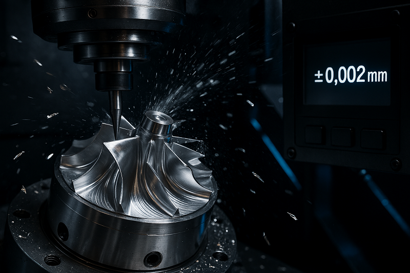
- Tight Tolerances: These are more restrictive tolerances, such as ±0.025 mm (±.001") or less. They are necessary for features requiring a high degree of precision, like bearing bores, mating surfaces, or high-speed rotating components. Achieving tight tolerances demands more advanced machinery, specialized tooling, slower machining speeds, and often, a controlled environment. Consequently, they are significantly more expensive to produce.
Understanding Dimensional Tolerances
The most basic and common type of tolerance, dimensional tolerance, controls the size of a feature. There are several ways to express it on a drawing:
- Bilateral Tolerance: Variation is permitted in both positive and negative directions from the nominal size (e.g., 20 mm ±0.05). This is common for external dimensions.
- Unilateral Tolerance: Variation is permitted in only one direction (e.g., 20 mm +0.00/-0.10). This is often used for hole-and-shaft assemblies to ensure a specific type of fit.
- Limit Tolerances: Instead of a deviation, the upper and lower limits are stated directly (e.g., 19.90 - 20.00 mm). This removes any ambiguity for the machinist and inspector.
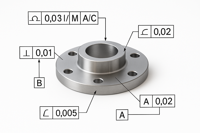
Exploring Geometric Dimensioning and Tolerancing (GD&T)
While dimensional tolerances control size, they don't control form or spatial relationships. A hole can be the right diameter but drilled at an angle. This is where Geometric Dimensioning and Tolerancing (GD&T) comes in. GD&T is a symbolic language used on engineering drawings to define the perfection of geometry. It controls a feature’s form, orientation, and location.
Form Tolerances: Controlling the Shape of a Feature
Form tolerances control the shape of a single feature without reference to any other feature or datum.
- Straightness: Ensures a line element on a surface or an axis is within a specified tolerance zone.
- Flatness: Specifies that all points on a surface must lie between two parallel planes.
- Circularity (Roundness): Controls how close a feature, like a circle or sphere, must be to its ideal geometric shape.
- Cylindricity: A 3D control that combines circularity and straightness to ensure a cylinder is round and not tapered.
Orientation Tolerances: Controlling the Angle Between Features
Orientation tolerances manage the angular relationship between two or more features. They must be related to a datum (a reference point, line, or plane).
- Perpendicularity: Ensures a feature is at a perfect 90° angle to a datum surface or axis.
- Parallelism: Specifies that a feature's surface or axis is equidistant at all points from a datum plane or axis.
- Angularity: Controls a feature's orientation at any specified angle (other than 90°) relative to a datum.
Location Tolerances: Controlling the Position of Features
Location tolerances are arguably the most important in GD&T, as they define where features are in relation to each other.
- Position (True Position): Defines a tolerance zone where the axis or center plane of a feature is permitted to vary from its "true" theoretical position.
- Concentricity: Controls the coaxiality of two cylindrical features, ensuring they share a common axis.
- Symmetry: Ensures that a feature is uniformly centered about the center plane of a datum feature.
Runout Tolerances: Controlling Variation During Rotation
Runout tolerances are used to control the variation of a surface as it rotates around a datum axis. They are crucial for shafts, bearings, and other rotating components.
- Circular Runout: Controls the form and position of a circular feature as it rotates 360°, managing wobble at a single point of measurement.
- Total Runout: A more comprehensive control that checks the variation across the entire surface of a feature as it rotates, controlling for cumulative variations in circularity, straightness, and taper.
Key Factors That Influence CNC Machining Tolerances
Multiple factors can affect the final accuracy of a machined part. Understanding them helps in designing for manufacturability (DFM).
- Machine Tool Accuracy: The inherent precision, rigidity, and thermal stability of the CNC machine itself are foundational. Regular maintenance and calibration are key.
- Material Properties: Softer materials like plastics can flex under cutting forces, while hard materials increase tool wear. Thermal expansion can also cause dimensional changes during machining.
- Tool Wear & Deflection: As a cutting tool wears down, it can no longer cut to the programmed dimension. Likewise, long or thin tools may deflect under pressure, causing inaccuracies.
- Workholding (Fixturing): The part must be held securely and without distortion. A poor clamping setup can lead to vibration, part movement, and dimensional errors.
- Heat & Vibration: The cutting process generates heat and vibration, both of which can impact the final surface finish and dimensional accuracy. Proper coolants and optimized cutting parameters are essential to manage this.
Best Practices for Specifying Tolerances
How you specify tolerances is as important as what you specify. Follow these guidelines to create clear, effective, and economical designs.
- Tolerance Only Where Necessary: The golden rule is to apply the loosest tolerance possible that still allows the part to function correctly. Avoid a blanket tight tolerance across the entire part.
- Leverage Standard Tolerances: For non-critical features, rely on the machine shop's standard tolerance or specify a general tolerance class like ISO 2768-m. This keeps costs down.
- Identify Critical-to-Function Features: Analyze your design and identify which features are essential for function—such as mating surfaces, bearing fits, and alignment holes. Apply tighter dimensional and geometric tolerances only to these areas.
- Consider the Cost Implications: Remember that each decimal place adds cost. Tighter tolerances lead to increased cycle times, special tooling, more complex setups, and higher inspection costs. Always perform a cost-benefit analysis.
ISO 2768 Standard Tolerance Table (Example)
Here is a simplified look at the ISO 2768-1 standard for linear dimensions, which provides tolerance classes.
| Basic Dimension (mm) | Fine (f) | Medium (m) | Coarse (c) | Very Coarse (v) |
|---|---|---|---|---|
| 0.5 up to 3 | ±0.05 | ±0.1 | ±0.2 | — |
| > 3 up to 6 | ±0.05 | ±0.1 | ±0.3 | ±0.5 |
| > 6 up to 30 | ±0.1 | ±0.2 | ±0.5 | ±1.0 |
| > 30 up to 120 | ±0.15 | ±0.3 | ±0.8 | ±1.5 |
| > 120 up to 400 | ±0.2 | ±0.5 | ±1.2 | ±2.5 |
For designs without specific tolerance callouts, many shops default to the 'medium' (m) class.
By mastering the principles of CNC machining tolerances, engineers and designers can create parts that are not only precise and functional but also economical to manufacture. Clear communication through well-toleranced drawings is the key to bridging the gap between design intent and manufacturing reality.

